
Homework Answers


Add Answer to:
(6) An air conditioner operates at 240V rms at a frequency of 60 Hz. It absorbs...
(a) Given a circuit in Figure Q4(a): (1) State the condition for maximum average power transfer...
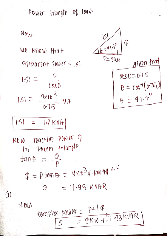
 (a) Given a circuit in Figure Q4(a): (1) State the condition for maximum average power transfer to the load impedance. Z (2 marks) (1) Determine the load impedance, Z (4 marks) (in) Find the maximum average power (5 marks) Lt mm JI R RE 492 120° A 20 C. 70.502 W ZL 1 Figure Q4(a) An air conditioner operates at 240V... at a frequency of 60 Hz. It absorbs an average power of 9 kW at a lagging power factor,...
Two loads, A and B, are connected in parallel across a 1-kV-rms 60-Hz line, as shown...
 Two loads, A and B, are connected in parallel
across a 1-kV-rms 60-Hz line, as shown in (Figure 1). Load
Aconsumes 10 kW with a 60 percent lagging power factor.
Load B has an apparent power of 20 kVA with an 80 percent
lagging power factor.
a) Find the power delivered by the source.
b) Find the reactive power delivered by the source.
c) Find the apparent power delivered by the source.
d) What is the power factor seen by...
Two loads, A and B, are connected in parallel
across a 1-kV-rms 60-Hz line, as shown in (Figure 1). Load
Aconsumes 10 kW with a 60 percent lagging power factor.
Load B has an apparent power of 20 kVA with an 80 percent
lagging power factor.
a) Find the power delivered by the source.
b) Find the reactive power delivered by the source.
c) Find the apparent power delivered by the source.
d) What is the power factor seen by...
A 60-Hz single-phase AC power network is shown in the figure below with four different loads. The source voltage ES-320 0. Prior to adding the capacitor load for power factor correction, the source c...
 A 60-Hz single-phase AC power network is shown in the figure below with four different loads. The source voltage ES-320 0. Prior to adding the capacitor load for power factor correction, the source current IS-135 30 . Determine the capacitance (in μF) of the capacitive load that will make the power factor unity (pf 1.0) of the system. Enter the one best answer (as a number without the units) from the following choices: Sync 74 % 6 15 kVA 10...
please take note the question is extend a) A single phase 240V 50Hz supply is supplying...
 please take note the question is extend
a) A single phase 240V 50Hz supply is supplying a power to a load which consist of 500 resistance and 0.3H inductance through a cable which has an effective impedance of 1+j2 0. The equivalent circuit of the single-phase system is shown in Figure Q1(a). Zcable=1+j2 I Load 5092 240V 50Hz Supply V Load 0.3H Figure Q1(a): A single phase system. i. ii. Determine the load current, low and the load voltage Vood...
please take note the question is extend
a) A single phase 240V 50Hz supply is supplying a power to a load which consist of 500 resistance and 0.3H inductance through a cable which has an effective impedance of 1+j2 0. The equivalent circuit of the single-phase system is shown in Figure Q1(a). Zcable=1+j2 I Load 5092 240V 50Hz Supply V Load 0.3H Figure Q1(a): A single phase system. i. ii. Determine the load current, low and the load voltage Vood...
1. A 480 V (rms) source supplies power to two loads connected in parallel. The first...
 1. A 480 V (rms) source supplies power to two loads connected in parallel. The first load draws 80 kW and 30 kVAR. The second load draws 100 kVA at a power factor of 0.6 lagging. a) Draw the power triangle for the first load and determine its power factor; b) Determine the current (both magnitude and phase, using the source voltage as the phase reference) drawn by the first load; c) Draw the power triangle for the second load...
can you answer this question and explain why? thanks. A 50-Hz 10-MVA, 66/22-kV distribution transformer has...
 can you answer this question and explain why?
thanks.
A 50-Hz 10-MVA, 66/22-kV distribution transformer has a full-load efficiency of 98% at 0.8 lagging power factor. The transformer core loss is 80 kW. The transformer supplies an industrial load that has a constant demand of 5000 kW at 0.65 lagging power factor. The cost of energy is $0.1 per kWh. 1. In the following questions, assume that the voltage at the load terminal is maintained constant at 22 kV. calculations....
can you answer this question and explain why?
thanks.
A 50-Hz 10-MVA, 66/22-kV distribution transformer has a full-load efficiency of 98% at 0.8 lagging power factor. The transformer core loss is 80 kW. The transformer supplies an industrial load that has a constant demand of 5000 kW at 0.65 lagging power factor. The cost of energy is $0.1 per kWh. 1. In the following questions, assume that the voltage at the load terminal is maintained constant at 22 kV. calculations....
VO) L1 L2 Line VO LI Power Calculations Learning Goal: In this tutorial, you will practice...
 VO) L1 L2 Line VO LI Power Calculations Learning Goal: In this tutorial, you will practice the calculation of power in circuits containing loads, including the effects of non-ideal transmission lines, and practice how to improve the power factor for an entire system. Many appliances (eg., hair dryers, coffee makers, and refrigerators) and industrial loads are powered by AC sources. The ability to be able to calculate their power needs is important in a number of situations. Before completing this...
Two balanced loads are connected to three phase supply via a feeder lines as shown below....
 Two balanced loads are connected to three phase supply via a feeder lines as shown below. The STAR load has a line voltage of 440 V, at 50 Hz. (Take 440/30% V as reference) F2 F2 F1 0.025 J0.142 B 0.0110 JO.05Ω Three Phase 65 kW Vi2 Load 2 Load 1 L1 DELTA PF = 0.72 440 30°V STAR Line Voltage LineVoltage | |Д|lagging Line Voltage STAR CONECTED Zo 2.80 + 13.270/Phase Determine: (i) The Line Current ; (ii) The...
4. A certain four-pole 240-V-rms 50-Hz delta-connected three-phase induction motor operates at slip 5% at full...
4. A certain four-pole 240-V-rms 50-Hz delta-connected three-phase induction motor operates at slip 5% at full load and has rotational losses (windage + friction) of 100 W. The stator resistance per phase is 0.2 Ohm. The results of no-load and locked-rotor tests on this motor are as follows: No-load test Locked-rotor test Line-to-line input voltage: 240 V 45 V Input active power: 1100 W 1300 W Input line current: 10 A 30 A Using the tests data, determine parameters of...
10. Two loads connected in parallel draw a total of 2.4 kW at 0.8 pflagging from...
 10. Two loads connected in parallel draw a total of 2.4 kW at 0.8 pflagging from a 120-V rms, 60- Hz line. One load absorbs 1.5 kW at a 0.707 pf lagging. Determine: (a) the pf of the second load, INV 11. Calculate the line currents for the system shown in figure. Calculate also the total power and reactive power consumed by the load. w 12. For the balanced three-phase circuit in Fig.. Calculate the line currents, the phase voltage...
 (a) Given a circuit in Figure Q4(a): (1) State the condition for maximum average power transfer to the load impedance. Z (2 marks) (1) Determine the load impedance, Z (4 marks) (in) Find the maximum average power (5 marks) Lt mm JI R RE 492 120° A 20 C. 70.502 W ZL 1 Figure Q4(a) An air conditioner operates at 240V... at a frequency of 60 Hz. It absorbs an average power of 9 kW at a lagging power factor,...
 Two loads, A and B, are connected in parallel
across a 1-kV-rms 60-Hz line, as shown in (Figure 1). Load
Aconsumes 10 kW with a 60 percent lagging power factor.
Load B has an apparent power of 20 kVA with an 80 percent
lagging power factor.
a) Find the power delivered by the source.
b) Find the reactive power delivered by the source.
c) Find the apparent power delivered by the source.
d) What is the power factor seen by...
Two loads, A and B, are connected in parallel
across a 1-kV-rms 60-Hz line, as shown in (Figure 1). Load
Aconsumes 10 kW with a 60 percent lagging power factor.
Load B has an apparent power of 20 kVA with an 80 percent
lagging power factor.
a) Find the power delivered by the source.
b) Find the reactive power delivered by the source.
c) Find the apparent power delivered by the source.
d) What is the power factor seen by...
 A 60-Hz single-phase AC power network is shown in the figure below with four different loads. The source voltage ES-320 0. Prior to adding the capacitor load for power factor correction, the source current IS-135 30 . Determine the capacitance (in μF) of the capacitive load that will make the power factor unity (pf 1.0) of the system. Enter the one best answer (as a number without the units) from the following choices: Sync 74 % 6 15 kVA 10...
 please take note the question is extend
a) A single phase 240V 50Hz supply is supplying a power to a load which consist of 500 resistance and 0.3H inductance through a cable which has an effective impedance of 1+j2 0. The equivalent circuit of the single-phase system is shown in Figure Q1(a). Zcable=1+j2 I Load 5092 240V 50Hz Supply V Load 0.3H Figure Q1(a): A single phase system. i. ii. Determine the load current, low and the load voltage Vood...
please take note the question is extend
a) A single phase 240V 50Hz supply is supplying a power to a load which consist of 500 resistance and 0.3H inductance through a cable which has an effective impedance of 1+j2 0. The equivalent circuit of the single-phase system is shown in Figure Q1(a). Zcable=1+j2 I Load 5092 240V 50Hz Supply V Load 0.3H Figure Q1(a): A single phase system. i. ii. Determine the load current, low and the load voltage Vood...
 1. A 480 V (rms) source supplies power to two loads connected in parallel. The first load draws 80 kW and 30 kVAR. The second load draws 100 kVA at a power factor of 0.6 lagging. a) Draw the power triangle for the first load and determine its power factor; b) Determine the current (both magnitude and phase, using the source voltage as the phase reference) drawn by the first load; c) Draw the power triangle for the second load...
 can you answer this question and explain why?
thanks.
A 50-Hz 10-MVA, 66/22-kV distribution transformer has a full-load efficiency of 98% at 0.8 lagging power factor. The transformer core loss is 80 kW. The transformer supplies an industrial load that has a constant demand of 5000 kW at 0.65 lagging power factor. The cost of energy is $0.1 per kWh. 1. In the following questions, assume that the voltage at the load terminal is maintained constant at 22 kV. calculations....
can you answer this question and explain why?
thanks.
A 50-Hz 10-MVA, 66/22-kV distribution transformer has a full-load efficiency of 98% at 0.8 lagging power factor. The transformer core loss is 80 kW. The transformer supplies an industrial load that has a constant demand of 5000 kW at 0.65 lagging power factor. The cost of energy is $0.1 per kWh. 1. In the following questions, assume that the voltage at the load terminal is maintained constant at 22 kV. calculations....
 VO) L1 L2 Line VO LI Power Calculations Learning Goal: In this tutorial, you will practice the calculation of power in circuits containing loads, including the effects of non-ideal transmission lines, and practice how to improve the power factor for an entire system. Many appliances (eg., hair dryers, coffee makers, and refrigerators) and industrial loads are powered by AC sources. The ability to be able to calculate their power needs is important in a number of situations. Before completing this...
 Two balanced loads are connected to three phase supply via a feeder lines as shown below. The STAR load has a line voltage of 440 V, at 50 Hz. (Take 440/30% V as reference) F2 F2 F1 0.025 J0.142 B 0.0110 JO.05Ω Three Phase 65 kW Vi2 Load 2 Load 1 L1 DELTA PF = 0.72 440 30°V STAR Line Voltage LineVoltage | |Д|lagging Line Voltage STAR CONECTED Zo 2.80 + 13.270/Phase Determine: (i) The Line Current ; (ii) The...
 10. Two loads connected in parallel draw a total of 2.4 kW at 0.8 pflagging from a 120-V rms, 60- Hz line. One load absorbs 1.5 kW at a 0.707 pf lagging. Determine: (a) the pf of the second load, INV 11. Calculate the line currents for the system shown in figure. Calculate also the total power and reactive power consumed by the load. w 12. For the balanced three-phase circuit in Fig.. Calculate the line currents, the phase voltage...
Most questions answered within 3 hours.
-
Where is the error in this code sequence?
String s1 = "Hello";
String s2 = "ello";...
asked 10 months ago -
Financial data for Joel de Paris, Inc., for last year
follow:
Joel de Paris, Inc.
Balance...
asked 10 months ago -
Consider this reaction:
Al2(SO4)3 (aq)+ BaCl3
(aq) Al2Cl6 (aq)- +
3BaSO4(s) . What is the...
asked 10 months ago -
Suppose that Savneet is considering increasing her
recent random sample from 20 car rentals to 40...
asked 10 months ago -
Trucks arrive at an unloading terminal at an average rate of 120
per hour.
Trucks arrive...
asked 10 months ago -
Why are methanol and ethanol completely soluble in water while
octanol is not very little soluble....
asked 10 months ago -
A facilities manager at a university reads in a research report
that the mean amount of...
asked 10 months ago -
When the CuSO4 is rehydrated by adding water to the anhydrous
compound, is this an endothermic...
asked 10 months ago -
A ray of sunlight is passing from diamond into crown glass; the
angle of incidence is...
asked 10 months ago -
A block of mass 0.249 kg is placed on top of a light, vertical
spring of...
asked 10 months ago -
how do the kidneys compensate in the presences of acidosis
a) trigger hyperventilate
b) reserve acid...
asked 10 months ago -
Question 501 pts
The rental rate of capital to the firm increases. Which of the
following...
asked 10 months ago