
Homework Answers

Please like if the answer is helpful..thank you...
Add Answer to:
A single-phase H-bridge topology below is operated with the input dc voltage Vdc=200 V, modulation index,...
bridge oad DC DC Vload DC For a single-phase DC-AC inverter with an RL load at the output. It is switching using the bi...
 bridge oad DC DC Vload DC For a single-phase DC-AC inverter with an RL load at the output. It is switching using the bipolar SPWM method with the desired fundamental frequency of 400 Hz and the switching frequency of 20.4 kHz. Here the modulation index is 0.6, input DC is 200 V, load R-5 Ω and L 2 mH a. What's the RMS value of the fundamental component of the output voltage across RL? b. What's the RMS value of...
1. Consider the single-phase VSI inverter shown below dc VR(t) iz(t) a) If your input voltage Vdc...
 1. Consider the single-phase VSI inverter shown below dc VR(t) iz(t) a) If your input voltage Vdc - 100V2 V and switching frequency is 60 Hz with zero delay angle. Then, sketch the square wave output. Mark the peak values [10 marks] b) Sketch the fundamental output on the top of the above waveform. Mark the peak value По marksl c) The above A VSI is used to create a square wave output with 100v2 V at 60 Hz. This...
Q1- The three-phase converter circuit of Fig. 1, Vd 300 V, is applied with PWM switching (mo 0.5, m 39), and the fund...
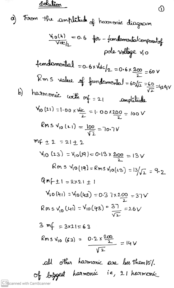
 Q1- The three-phase converter circuit of Fig. 1, Vd 300 V, is applied with PWM switching (mo 0.5, m 39), and the fundamental frequency is 50 Hz. Calculate the rms values of the fundamental-frequency voltage and some of the dominant harmonics in the line voltage (line-to-line). The generalized harmonic lookup table is given below the diagram. S1 S5 dc Fig. 1 Table 8-2 Generalized Harmonics of vL for a Large and Odd m/ That Is a Multiple of 3 0.2...
Example 1: Switch-mode inverter (one phase-leg, half bridge) A general analysis of the switch-mod...
 Example 1: Switch-mode inverter (one phase-leg, half bridge) A general analysis of the switch-mode inverter (shown in the figure below) is to be done. The switching frequency f, which is also the frequency of the triangular signal is 1450 Hz. The DC voltage, Vd, is 600 V. Output voltage is sinusoidal voltage with a frequency equal to 50 Hz. The load is connected between the inverter leg A and the dc voltage midpoint o. A+ A+ A V Find the...
Re-submission of question. Consider the Full-bridge single-phase inverter with input voltage equal to 100V. This inverter...
Re-submission of question. Consider the Full-bridge single-phase inverter with input voltage equal to 100V. This inverter is controlled by single PWM technique with amplitude modulalation index equal to 0.5 to generate a 3-level half-wave symmetry waveform with frequency equal to 50 Hz. (a) Draw its power circuit. [solved by an expert] (b) Obtain the switching table. [ solved by an expert] (c) Calculate the width of each generated pulses at the output voltage.[solved by an expert] (d) Calculate the RMS...
 bridge oad DC DC Vload DC For a single-phase DC-AC inverter with an RL load at the output. It is switching using the bipolar SPWM method with the desired fundamental frequency of 400 Hz and the switching frequency of 20.4 kHz. Here the modulation index is 0.6, input DC is 200 V, load R-5 Ω and L 2 mH a. What's the RMS value of the fundamental component of the output voltage across RL? b. What's the RMS value of...
 1. Consider the single-phase VSI inverter shown below dc VR(t) iz(t) a) If your input voltage Vdc - 100V2 V and switching frequency is 60 Hz with zero delay angle. Then, sketch the square wave output. Mark the peak values [10 marks] b) Sketch the fundamental output on the top of the above waveform. Mark the peak value По marksl c) The above A VSI is used to create a square wave output with 100v2 V at 60 Hz. This...
 Q1- The three-phase converter circuit of Fig. 1, Vd 300 V, is applied with PWM switching (mo 0.5, m 39), and the fundamental frequency is 50 Hz. Calculate the rms values of the fundamental-frequency voltage and some of the dominant harmonics in the line voltage (line-to-line). The generalized harmonic lookup table is given below the diagram. S1 S5 dc Fig. 1 Table 8-2 Generalized Harmonics of vL for a Large and Odd m/ That Is a Multiple of 3 0.2...
 Example 1: Switch-mode inverter (one phase-leg, half bridge) A general analysis of the switch-mode inverter (shown in the figure below) is to be done. The switching frequency f, which is also the frequency of the triangular signal is 1450 Hz. The DC voltage, Vd, is 600 V. Output voltage is sinusoidal voltage with a frequency equal to 50 Hz. The load is connected between the inverter leg A and the dc voltage midpoint o. A+ A+ A V Find the...
Most questions answered within 3 hours.
-
Where is the error in this code sequence?
String s1 = "Hello";
String s2 = "ello";...
asked 10 months ago -
Financial data for Joel de Paris, Inc., for last year
follow:
Joel de Paris, Inc.
Balance...
asked 10 months ago -
Consider this reaction:
Al2(SO4)3 (aq)+ BaCl3
(aq) Al2Cl6 (aq)- +
3BaSO4(s) . What is the...
asked 10 months ago -
Suppose that Savneet is considering increasing her
recent random sample from 20 car rentals to 40...
asked 10 months ago -
Trucks arrive at an unloading terminal at an average rate of 120
per hour.
Trucks arrive...
asked 10 months ago -
Why are methanol and ethanol completely soluble in water while
octanol is not very little soluble....
asked 10 months ago -
A facilities manager at a university reads in a research report
that the mean amount of...
asked 10 months ago -
When the CuSO4 is rehydrated by adding water to the anhydrous
compound, is this an endothermic...
asked 10 months ago -
A ray of sunlight is passing from diamond into crown glass; the
angle of incidence is...
asked 10 months ago -
A block of mass 0.249 kg is placed on top of a light, vertical
spring of...
asked 10 months ago -
how do the kidneys compensate in the presences of acidosis
a) trigger hyperventilate
b) reserve acid...
asked 10 months ago -
Question 501 pts
The rental rate of capital to the firm increases. Which of the
following...
asked 10 months ago