
Homework Answers


Add Answer to:
using Mohris Circle Determine a) & Principle stresses at point A b) - Represent the state...
11.80 MPa ニ62.29 MPa Determine the stresses for the oriented element in e 30° from the original position in the counter clockwise direction by using Mohr circle and represent the stress state. 60° 6...
 11.80 MPa ニ62.29 MPa Determine the stresses for the oriented element in e 30° from the original position in the counter clockwise direction by using Mohr circle and represent the stress state. 60° 60 Young's Modulus (GPa) 73 Matera Yield Stress Ultimate Stress Y PoissonDensity Ratio kg/m3 2780 (MPa) 324 (MPa) 469 Al 2024-T4 0.33 (Check it) '* 49.96 MPa --5.87 MPa に21.69 MPa x'
11.80 MPa ニ62.29 MPa Determine the stresses for the oriented element in e 30° from...
11.80 MPa ニ62.29 MPa Determine the stresses for the oriented element in e 30° from the original position in the counter clockwise direction by using Mohr circle and represent the stress state. 60° 60 Young's Modulus (GPa) 73 Matera Yield Stress Ultimate Stress Y PoissonDensity Ratio kg/m3 2780 (MPa) 324 (MPa) 469 Al 2024-T4 0.33 (Check it) '* 49.96 MPa --5.87 MPa に21.69 MPa x'
11.80 MPa ニ62.29 MPa Determine the stresses for the oriented element in e 30° from...
Using Mohr's circle determine for the below differential element: a) the principal stresses and the plan...
 Using Mohr's circle determine for the below differential
element:
a) the principal stresses and the plan on which they act. Show
the stresses on a properly oriented differential element. Label all
stresses.
b) the maximum shear stress and the plan on which they act. Show
the stresses on a properly oriented differential element. Label all
stresses.
c) the stresses on a differential element 40 degrees clockwise
from the original element. Show the stresses on a properly oriented
differential element. Label...
Using Mohr's circle determine for the below differential
element:
a) the principal stresses and the plan on which they act. Show
the stresses on a properly oriented differential element. Label all
stresses.
b) the maximum shear stress and the plan on which they act. Show
the stresses on a properly oriented differential element. Label all
stresses.
c) the stresses on a differential element 40 degrees clockwise
from the original element. Show the stresses on a properly oriented
differential element. Label...
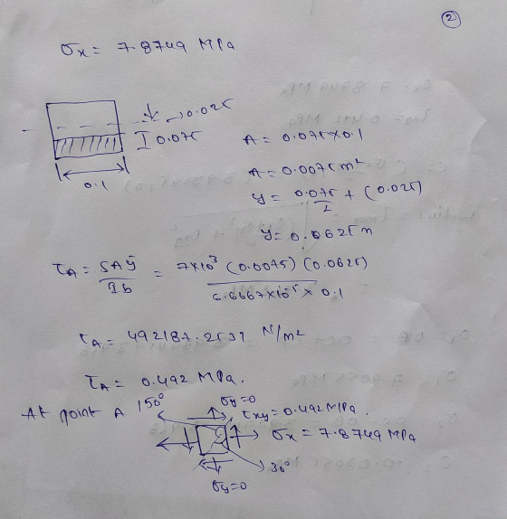
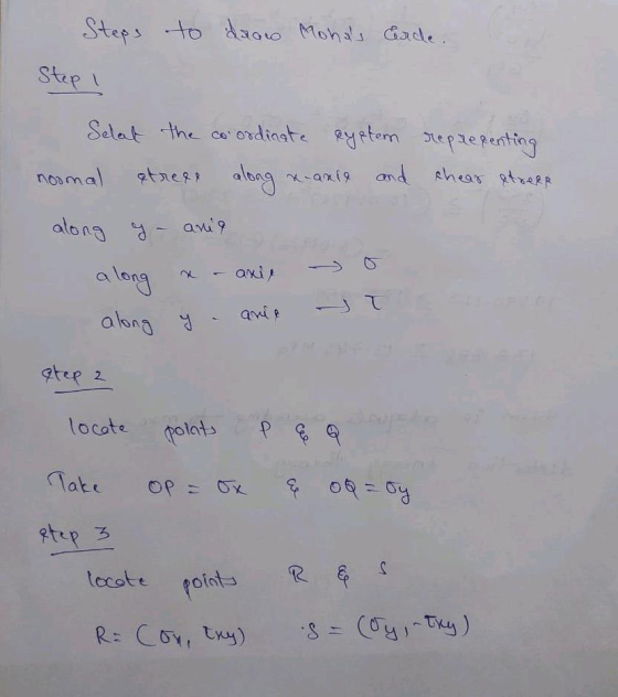
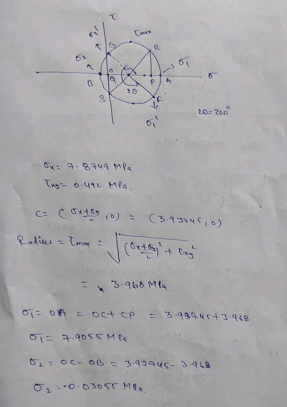
draw mohr circle 3 kN/m 300 mm 30° 75 mm 200 mm Determine the principal stresses...
 draw mohr circle
3 kN/m 300 mm 30° 75 mm 200 mm Determine the principal stresses at point A and specify the orientation of element. PROBLEM # 5 FA-3x4-12kN 2m Br B, 3.428 kN 2m 3.428KN -May. = 6.857 x 1-75 = 1.1428 N/mm"(7) mm (7) 200:300厂= 1.1428 N/ mm 300 12 bi 4 0.06428 N/mm2 6x3.4428x10 300 ) 200x 300 4 200
draw mohr circle
3 kN/m 300 mm 30° 75 mm 200 mm Determine the principal stresses at point A and specify the orientation of element. PROBLEM # 5 FA-3x4-12kN 2m Br B, 3.428 kN 2m 3.428KN -May. = 6.857 x 1-75 = 1.1428 N/mm"(7) mm (7) 200:300厂= 1.1428 N/ mm 300 12 bi 4 0.06428 N/mm2 6x3.4428x10 300 ) 200x 300 4 200
For the joint and loading shown, determine the stress states at points A and B on...
 For the joint and loading shown, determine the stress states at
points A and B on section-aa, and the principle stresses at point
A. The free-body diagram including section-aa is given below for
your convenience. Section-aa has a rectangular cross-section area
of thickness 12 mm (shown) and width 18 mm. a) Sketch each stress
state using a square stress element. b) Determine the principle
stresses at point A (no need to sketch the stress
element).
Problem 1: (25%) For the...
For the joint and loading shown, determine the stress states at
points A and B on section-aa, and the principle stresses at point
A. The free-body diagram including section-aa is given below for
your convenience. Section-aa has a rectangular cross-section area
of thickness 12 mm (shown) and width 18 mm. a) Sketch each stress
state using a square stress element. b) Determine the principle
stresses at point A (no need to sketch the stress
element).
Problem 1: (25%) For the...
(17 Marks) 0.2. The state of plane stress at a point is shown on the element in the figure below. 50 MFa 1. Construct its representative Mohr's circle and specify its reference line. 2. Determ...
 (17 Marks) 0.2. The state of plane stress at a point is shown on the element in the figure below. 50 MFa 1. Construct its representative Mohr's circle and specify its reference line. 2. Determine the orientation of an element at this point and subjected to the principle stresses. Show the result on the element. 40 SMPa 70 MPa 3. Determine the equivalent state of stress for an element oriented 20 clockwise from the element shown. Show the result on...
Problem 6 (15 points) The state of plane stress at a point is shown on the...
 Problem 6 (15 points) The state of plane stress at a point is shown on the element in Figure 6. a. Using Mohr's circle, determine the principal stresses and the maximum in-plane shear stress and average normal stress. Specify the orientation of the element in each case. b. Represent the state of stress on an element oriented 30° counterclockwise from the position shown in Figure 6. 20 MPa 100 MPa 40 MPa Figure 6 (plot Mohr's circle on the next...
Problem No. 5 (Figure 5) Using Mohr's circle determine the following: (i) Maximum principle stresses (σ1...
 Problem No. 5 (Figure 5) Using Mohr's circle determine the following: (i) Maximum principle stresses (σ1 and σ2) (i) Maximum shear stress (Tmax) (iii) Orientation of principle axis (%) (iv) Orientation of Tmax (0s) (v) Determine σ' and σ' for θ 15. clockwise rotation (vi) Sketch the state of stress for case- (ii) (vii) Sketch the state of stress for case- (iv) Figure 5 2 ksi 2 ksi 4 ksi
The stresses on element A are as shown. Using Mohrs circle: a) Determine the stresses on...
 The stresses on element A are as shown. Using Mohrs circle: a) Determine the stresses on element B and show these on a sketch of a properly oriented element. b) Determine the principal stresses and show these on a sketch of a properly oriented element. c) Determine the maximum and minimum shear stresses and associated normal stresses and show these on a sketch of a properly oriented element. у Y1 4.0 MPa 2.0 MPa A B 35° 1 1.0 MPa...
PROBLEM 4: Continued Part2: The state of stress at a point represented on the Mohr's circle...
 PROBLEM 4: Continued Part2: The state of stress at a point represented on the Mohr's circle shown below as point X (- 200 MPa, -200 MPa) and y. The center of the circle has a coordinate C (50,0) and a radius R=320 MPa. Determine the normal stress Ox' and the shear stress t x'y on an element oriented 0=10 degrees clockwise from x. 16% (-200, -200) 20 R 01 to +T
with drawings Question 4 (CLO5) (6 points) The state of the stress at a point is...
 with drawings
Question 4 (CLO5) (6 points) The state of the stress at a point is shown on the element. Determine the following: (a) The principal stresses, and the corresponding orientation of the element (b) The maximum in-plane shear stress and the associated average normal stress at the point. Show the corresponding orientation of the element. (c) Using Mohr's circle (only), determine the stress components at the same point on another element oriented 30° counterclockwise from the position shown. Draw...
with drawings
Question 4 (CLO5) (6 points) The state of the stress at a point is shown on the element. Determine the following: (a) The principal stresses, and the corresponding orientation of the element (b) The maximum in-plane shear stress and the associated average normal stress at the point. Show the corresponding orientation of the element. (c) Using Mohr's circle (only), determine the stress components at the same point on another element oriented 30° counterclockwise from the position shown. Draw...
 11.80 MPa ニ62.29 MPa Determine the stresses for the oriented element in e 30° from the original position in the counter clockwise direction by using Mohr circle and represent the stress state. 60° 60 Young's Modulus (GPa) 73 Matera Yield Stress Ultimate Stress Y PoissonDensity Ratio kg/m3 2780 (MPa) 324 (MPa) 469 Al 2024-T4 0.33 (Check it) '* 49.96 MPa --5.87 MPa に21.69 MPa x'
11.80 MPa ニ62.29 MPa Determine the stresses for the oriented element in e 30° from...
11.80 MPa ニ62.29 MPa Determine the stresses for the oriented element in e 30° from the original position in the counter clockwise direction by using Mohr circle and represent the stress state. 60° 60 Young's Modulus (GPa) 73 Matera Yield Stress Ultimate Stress Y PoissonDensity Ratio kg/m3 2780 (MPa) 324 (MPa) 469 Al 2024-T4 0.33 (Check it) '* 49.96 MPa --5.87 MPa に21.69 MPa x'
11.80 MPa ニ62.29 MPa Determine the stresses for the oriented element in e 30° from...
 Using Mohr's circle determine for the below differential
element:
a) the principal stresses and the plan on which they act. Show
the stresses on a properly oriented differential element. Label all
stresses.
b) the maximum shear stress and the plan on which they act. Show
the stresses on a properly oriented differential element. Label all
stresses.
c) the stresses on a differential element 40 degrees clockwise
from the original element. Show the stresses on a properly oriented
differential element. Label...
Using Mohr's circle determine for the below differential
element:
a) the principal stresses and the plan on which they act. Show
the stresses on a properly oriented differential element. Label all
stresses.
b) the maximum shear stress and the plan on which they act. Show
the stresses on a properly oriented differential element. Label all
stresses.
c) the stresses on a differential element 40 degrees clockwise
from the original element. Show the stresses on a properly oriented
differential element. Label...
 draw mohr circle
3 kN/m 300 mm 30° 75 mm 200 mm Determine the principal stresses at point A and specify the orientation of element. PROBLEM # 5 FA-3x4-12kN 2m Br B, 3.428 kN 2m 3.428KN -May. = 6.857 x 1-75 = 1.1428 N/mm"(7) mm (7) 200:300厂= 1.1428 N/ mm 300 12 bi 4 0.06428 N/mm2 6x3.4428x10 300 ) 200x 300 4 200
draw mohr circle
3 kN/m 300 mm 30° 75 mm 200 mm Determine the principal stresses at point A and specify the orientation of element. PROBLEM # 5 FA-3x4-12kN 2m Br B, 3.428 kN 2m 3.428KN -May. = 6.857 x 1-75 = 1.1428 N/mm"(7) mm (7) 200:300厂= 1.1428 N/ mm 300 12 bi 4 0.06428 N/mm2 6x3.4428x10 300 ) 200x 300 4 200
 For the joint and loading shown, determine the stress states at
points A and B on section-aa, and the principle stresses at point
A. The free-body diagram including section-aa is given below for
your convenience. Section-aa has a rectangular cross-section area
of thickness 12 mm (shown) and width 18 mm. a) Sketch each stress
state using a square stress element. b) Determine the principle
stresses at point A (no need to sketch the stress
element).
Problem 1: (25%) For the...
For the joint and loading shown, determine the stress states at
points A and B on section-aa, and the principle stresses at point
A. The free-body diagram including section-aa is given below for
your convenience. Section-aa has a rectangular cross-section area
of thickness 12 mm (shown) and width 18 mm. a) Sketch each stress
state using a square stress element. b) Determine the principle
stresses at point A (no need to sketch the stress
element).
Problem 1: (25%) For the...
 (17 Marks) 0.2. The state of plane stress at a point is shown on the element in the figure below. 50 MFa 1. Construct its representative Mohr's circle and specify its reference line. 2. Determine the orientation of an element at this point and subjected to the principle stresses. Show the result on the element. 40 SMPa 70 MPa 3. Determine the equivalent state of stress for an element oriented 20 clockwise from the element shown. Show the result on...
 Problem 6 (15 points) The state of plane stress at a point is shown on the element in Figure 6. a. Using Mohr's circle, determine the principal stresses and the maximum in-plane shear stress and average normal stress. Specify the orientation of the element in each case. b. Represent the state of stress on an element oriented 30° counterclockwise from the position shown in Figure 6. 20 MPa 100 MPa 40 MPa Figure 6 (plot Mohr's circle on the next...
 Problem No. 5 (Figure 5) Using Mohr's circle determine the following: (i) Maximum principle stresses (σ1 and σ2) (i) Maximum shear stress (Tmax) (iii) Orientation of principle axis (%) (iv) Orientation of Tmax (0s) (v) Determine σ' and σ' for θ 15. clockwise rotation (vi) Sketch the state of stress for case- (ii) (vii) Sketch the state of stress for case- (iv) Figure 5 2 ksi 2 ksi 4 ksi
 The stresses on element A are as shown. Using Mohrs circle: a) Determine the stresses on element B and show these on a sketch of a properly oriented element. b) Determine the principal stresses and show these on a sketch of a properly oriented element. c) Determine the maximum and minimum shear stresses and associated normal stresses and show these on a sketch of a properly oriented element. у Y1 4.0 MPa 2.0 MPa A B 35° 1 1.0 MPa...
 PROBLEM 4: Continued Part2: The state of stress at a point represented on the Mohr's circle shown below as point X (- 200 MPa, -200 MPa) and y. The center of the circle has a coordinate C (50,0) and a radius R=320 MPa. Determine the normal stress Ox' and the shear stress t x'y on an element oriented 0=10 degrees clockwise from x. 16% (-200, -200) 20 R 01 to +T
 with drawings
Question 4 (CLO5) (6 points) The state of the stress at a point is shown on the element. Determine the following: (a) The principal stresses, and the corresponding orientation of the element (b) The maximum in-plane shear stress and the associated average normal stress at the point. Show the corresponding orientation of the element. (c) Using Mohr's circle (only), determine the stress components at the same point on another element oriented 30° counterclockwise from the position shown. Draw...
with drawings
Question 4 (CLO5) (6 points) The state of the stress at a point is shown on the element. Determine the following: (a) The principal stresses, and the corresponding orientation of the element (b) The maximum in-plane shear stress and the associated average normal stress at the point. Show the corresponding orientation of the element. (c) Using Mohr's circle (only), determine the stress components at the same point on another element oriented 30° counterclockwise from the position shown. Draw...
Most questions answered within 3 hours.
-
Where is the error in this code sequence?
String s1 = "Hello";
String s2 = "ello";...
asked 10 months ago -
Financial data for Joel de Paris, Inc., for last year
follow:
Joel de Paris, Inc.
Balance...
asked 10 months ago -
Consider this reaction:
Al2(SO4)3 (aq)+ BaCl3
(aq) Al2Cl6 (aq)- +
3BaSO4(s) . What is the...
asked 10 months ago -
Suppose that Savneet is considering increasing her
recent random sample from 20 car rentals to 40...
asked 10 months ago -
Trucks arrive at an unloading terminal at an average rate of 120
per hour.
Trucks arrive...
asked 10 months ago -
Why are methanol and ethanol completely soluble in water while
octanol is not very little soluble....
asked 10 months ago -
A facilities manager at a university reads in a research report
that the mean amount of...
asked 10 months ago -
When the CuSO4 is rehydrated by adding water to the anhydrous
compound, is this an endothermic...
asked 10 months ago -
A ray of sunlight is passing from diamond into crown glass; the
angle of incidence is...
asked 10 months ago -
A block of mass 0.249 kg is placed on top of a light, vertical
spring of...
asked 10 months ago -
how do the kidneys compensate in the presences of acidosis
a) trigger hyperventilate
b) reserve acid...
asked 10 months ago -
Question 501 pts
The rental rate of capital to the firm increases. Which of the
following...
asked 10 months ago