True or False? The maximum positive bending moment in a simply-supported beam loaded with a uniform...
True or False?
The maximum positive bending moment in a simply-supported beam loaded with a uniform downward distributed load is at the supports. [Choose ONE]
Homework Answers
And - False
Because in simply supported beam maximum bending moment occurs
at midspan of the beam and zero bending moment occurs at the
support.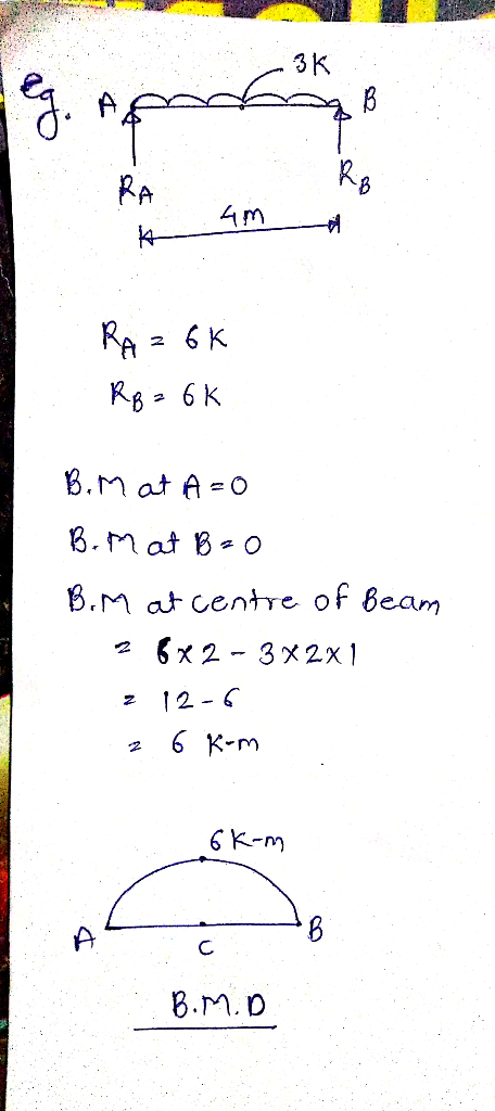
Add Answer to:
True or False?
The maximum positive bending moment in a simply-supported beam
loaded with a uniform...
The W33 x221 steel simply supported beam is loaded with concentrated loads and uniform load as...
 The W33 x221 steel simply supported beam is loaded with
concentrated loads and uniform
load as shown with the load P= 150kip and w = 10kip/ft. For
this beam do the following;
a) Draw the shear and bending moment diagram
b) Calculate the maximum compressive and tensile stress
c) Calculate the maximum shear stress
P Р 3 ft 3 ft w 10 ft
The W33 x221 steel simply supported beam is loaded with
concentrated loads and uniform
load as shown with the load P= 150kip and w = 10kip/ft. For
this beam do the following;
a) Draw the shear and bending moment diagram
b) Calculate the maximum compressive and tensile stress
c) Calculate the maximum shear stress
P Р 3 ft 3 ft w 10 ft
Shear force and bending moments of the beam. For the simply supported beam subjected to the...
 Shear force and bending moments of the beam.
For the simply supported beam subjected to the loading shown in Figure P7.8 derive equations for the shear force V and the bending moment M for any location in the beam. (Place the origin at point A.) plot the shear-force and bending-moment diagrams for the beam, using the derived functions. report the maximum positive bending moment, the maximum negative bending moment, and their respective locations.
Shear force and bending moments of the beam.
For the simply supported beam subjected to the loading shown in Figure P7.8 derive equations for the shear force V and the bending moment M for any location in the beam. (Place the origin at point A.) plot the shear-force and bending-moment diagrams for the beam, using the derived functions. report the maximum positive bending moment, the maximum negative bending moment, and their respective locations.
A loaded beam ABCDE is simply supported at B and D and carries point loads of...
A loaded beam ABCDE is simply supported at B and D and carries point loads of 40 kN, 80 kN, and 60 kN at A, C, and E respectively, together with a uniformly distributed load of 20 kN/m between B and D. AB = DE = 1 m, and BC = CD = 4 m. Find the dimensions of a suitable W – Shape beam to restrict the maximum bending stress in the beam to 140 N/mm2. Ignore the mass...
Consider the simply supported beam and loaded as shown in the M figure. Perform the following:...
 Consider the simply supported beam and loaded as shown in the M figure. Perform the following: 1. Determine the support reactions. 2. Plot SFD and BMD 3. if L=9 m, the beam will fail when the maximum shear force is Vmax= 5 kN or the maximum bending moment is Mmax=22 kN.m. Determine the largest couple moment Mo the beam will support.
Question 1 (6.7 points) AW12 x 50 steel beam is used as a simply supported beam...
 Question 1 (6.7 points) AW12 x 50 steel beam is used as a simply supported beam on span of 24 feet. The beam supports a uniformly distributed load of 1000 lb/ft. Calculate the maximum bending stress. a) 9,560 psi Ob) 11,280 psi Oc) 13,460 psi d) none of the above Question 2 (6.7 points) Determine the number of 2 x 12's that need to be nailed together to build a beam that would support a uniform load of 500 lb/ft...
3. A simply supported beam is loaded as shown. Determine the maximum deflection of the beam,...
 3. A simply supported beam is loaded as shown. Determine the maximum deflection of the beam, and slope at A. Use any of the three methods: 1) double integration, 2) moment-area, or 3) conjugate beam 5k 5K (20) DJ E = 29x10° psi I = 600 in4 klokt kloft * loft &
A simply supported beam as shown in the figure. The beam section is W18x211. The beam...
 A simply supported beam as shown in the figure. The beam section is W18x211. The beam must support its own weight and must carry the following loading: Super-imposed distributed dead load = 0.25 kip/ft Distributed live load = 1 kip/ft Concentrated dead load = 12 kip The beam span L = 26 ft and the distance of the concentrated load from the right support a=6 ft. Consider analy- sis of beam subjected to load combination 1.2 dead + 1.6 live....
A rectangular cross section at a location along a beam in bending is
 (a). A rectangular cross section at a location along a beam in bending is acted upon by a bending moment and a shear force. The cross section is \(120 \mathrm{~mm}\) wide, \(300 \mathrm{~mm}\) deep and is orientated such that it is in bending about its major axis of bending. The magnitudes of the bending moment and shear force are \(315 \mathrm{kNm}\) and \(240 \mathrm{kN}\) respectively. Determine the maximum bending and shear stresses on the cross section. Plot the bending and...
The simply supported beam, with a U cross section, is subjected to a uniformly distributed force...
 The simply supported beam, with a U cross section, is subjected to a uniformly distributed force of 8 kN/m and a concentrated load of 12 kN as shown. (a) Determine the reaction at supports A and B, (b) sketch the shear diagram and the moment diagram, (c) determine the location of the neutral axis of the cross section and calculate its area moment of inertia about the neutral axis, and (d) determine absolute maximum bending stress and (e) absolute maximum...
2. A 30 ft long simply supported beam supports a uniformly distributed load of 2 kips/ft...
 2. A 30 ft long simply supported beam supports a uniformly distributed load of 2 kips/ft over the entire span. The beam and cross section are shown below. Draw the shear and moment diagrams, find the neutral axis location, moment of inertia of the composite section, the maximum bending stress on the cross section. (40 points) 10" 2 k/ft 1-3" 30'-0"
 The W33 x221 steel simply supported beam is loaded with
concentrated loads and uniform
load as shown with the load P= 150kip and w = 10kip/ft. For
this beam do the following;
a) Draw the shear and bending moment diagram
b) Calculate the maximum compressive and tensile stress
c) Calculate the maximum shear stress
P Р 3 ft 3 ft w 10 ft
The W33 x221 steel simply supported beam is loaded with
concentrated loads and uniform
load as shown with the load P= 150kip and w = 10kip/ft. For
this beam do the following;
a) Draw the shear and bending moment diagram
b) Calculate the maximum compressive and tensile stress
c) Calculate the maximum shear stress
P Р 3 ft 3 ft w 10 ft
 Shear force and bending moments of the beam.
For the simply supported beam subjected to the loading shown in Figure P7.8 derive equations for the shear force V and the bending moment M for any location in the beam. (Place the origin at point A.) plot the shear-force and bending-moment diagrams for the beam, using the derived functions. report the maximum positive bending moment, the maximum negative bending moment, and their respective locations.
Shear force and bending moments of the beam.
For the simply supported beam subjected to the loading shown in Figure P7.8 derive equations for the shear force V and the bending moment M for any location in the beam. (Place the origin at point A.) plot the shear-force and bending-moment diagrams for the beam, using the derived functions. report the maximum positive bending moment, the maximum negative bending moment, and their respective locations.
 Consider the simply supported beam and loaded as shown in the M figure. Perform the following: 1. Determine the support reactions. 2. Plot SFD and BMD 3. if L=9 m, the beam will fail when the maximum shear force is Vmax= 5 kN or the maximum bending moment is Mmax=22 kN.m. Determine the largest couple moment Mo the beam will support.
 Question 1 (6.7 points) AW12 x 50 steel beam is used as a simply supported beam on span of 24 feet. The beam supports a uniformly distributed load of 1000 lb/ft. Calculate the maximum bending stress. a) 9,560 psi Ob) 11,280 psi Oc) 13,460 psi d) none of the above Question 2 (6.7 points) Determine the number of 2 x 12's that need to be nailed together to build a beam that would support a uniform load of 500 lb/ft...
 3. A simply supported beam is loaded as shown. Determine the maximum deflection of the beam, and slope at A. Use any of the three methods: 1) double integration, 2) moment-area, or 3) conjugate beam 5k 5K (20) DJ E = 29x10° psi I = 600 in4 klokt kloft * loft &
 A simply supported beam as shown in the figure. The beam section is W18x211. The beam must support its own weight and must carry the following loading: Super-imposed distributed dead load = 0.25 kip/ft Distributed live load = 1 kip/ft Concentrated dead load = 12 kip The beam span L = 26 ft and the distance of the concentrated load from the right support a=6 ft. Consider analy- sis of beam subjected to load combination 1.2 dead + 1.6 live....
 2. A 30 ft long simply supported beam supports a uniformly distributed load of 2 kips/ft over the entire span. The beam and cross section are shown below. Draw the shear and moment diagrams, find the neutral axis location, moment of inertia of the composite section, the maximum bending stress on the cross section. (40 points) 10" 2 k/ft 1-3" 30'-0"
Most questions answered within 3 hours.
-
Where is the error in this code sequence?
String s1 = "Hello";
String s2 = "ello";...
asked 10 months ago -
Financial data for Joel de Paris, Inc., for last year
follow:
Joel de Paris, Inc.
Balance...
asked 10 months ago -
Consider this reaction:
Al2(SO4)3 (aq)+ BaCl3
(aq) Al2Cl6 (aq)- +
3BaSO4(s) . What is the...
asked 10 months ago -
Suppose that Savneet is considering increasing her
recent random sample from 20 car rentals to 40...
asked 10 months ago -
Trucks arrive at an unloading terminal at an average rate of 120
per hour.
Trucks arrive...
asked 10 months ago -
Why are methanol and ethanol completely soluble in water while
octanol is not very little soluble....
asked 10 months ago -
A facilities manager at a university reads in a research report
that the mean amount of...
asked 10 months ago -
When the CuSO4 is rehydrated by adding water to the anhydrous
compound, is this an endothermic...
asked 10 months ago -
A ray of sunlight is passing from diamond into crown glass; the
angle of incidence is...
asked 10 months ago -
A block of mass 0.249 kg is placed on top of a light, vertical
spring of...
asked 10 months ago -
how do the kidneys compensate in the presences of acidosis
a) trigger hyperventilate
b) reserve acid...
asked 10 months ago -
Question 501 pts
The rental rate of capital to the firm increases. Which of the
following...
asked 10 months ago