Explain the difference between a latch and an edge-triggered flip-flop – use timing diagrams in your...
Explain the difference between a latch and an edge-triggered flip-flop – use timing diagrams in your explanation.
Homework Answers
1. Both latches and flip-flops are circuit elements whose output depends not only on the present inputs, but also on previous inputs and outputs.
2. They both are hence referred as "sequential" elements.
3. Latches are level sensitive i.e. the output captures the input when the clock signal is high, so as long as the clock is logic 1, the output can change if the input also changes.
4. Flip-Flops are edge sensitive i.e. flip flop will store the input only when there is a rising or falling edge of the clock.
5. A positive level latch is transparent to the positive level(enable), and it latches the final input before it is changing its level(i.e. before enable goes to '0' or before the clock goes to -ve level.)
6. A positive edge flop will have its output effective when the clock input changes from '0' to '1' state ('1' to '0' for negative edge flop) only.
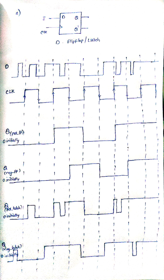
In the above figure the waveforms are as follows.
1. Positive edge triggered flip flop
2. Negative edge triggered flip flop
3. Positive level sensitive Latch
4. Negative level sensitive Latch
Add Answer to:
Explain the difference between a latch and an edge-triggered
flip-flop – use timing diagrams in your...
a) (5 marks) Explain the difference between a latch, a gated latch and a flip flop....
 a) (5 marks) Explain the difference between a latch, a gated latch and a flip flop. b) (5 marks) A gated SR latch has the following schematic diagram CLK a) Draw a timing diagram showing the Q and Q outputs for the following sequence of inputs: CLK R Assume that the initial state of the outputs is Q 0 and Q 1 c) (5 marks) Draw a schematic diagram for a rising edge-triggered master-slave D flip- flop built using two...
All flip flops are positive-edge triggered. Assume each flip flop starts at 0.
 All flip flops are
positive-edge triggered. Assume each flip flop starts at 0.
Problem 11: (8 pts) For the following circuit, complete the timing diagram for the state of each flip flop and the output, where shown. All flip flops are positive-edge triggered. Assume each flip flop starts at 0. J-K FF TFF CLK PRE CLR PRE CLR CLR回 Clock CLR
Problem 11: (8 pts) For the following circuit, complete the timing diagram for the state of each flip flop...
All flip flops are
positive-edge triggered. Assume each flip flop starts at 0.
Problem 11: (8 pts) For the following circuit, complete the timing diagram for the state of each flip flop and the output, where shown. All flip flops are positive-edge triggered. Assume each flip flop starts at 0. J-K FF TFF CLK PRE CLR PRE CLR CLR回 Clock CLR
Problem 11: (8 pts) For the following circuit, complete the timing diagram for the state of each flip flop...
Draw waveforms for the indicated latch and flip-flop outputs. The initial value for each output is...
 Draw waveforms for the indicated latch and flip-flop outputs.
The initial value for each output is 0 as shown.
CLK D Transparent low latch Q Transparent high latch Q Negative Edge Triggered Flip-flop Q Positive Edge Triggered Flip-flop Q
Draw waveforms for the indicated latch and flip-flop outputs.
The initial value for each output is 0 as shown.
CLK D Transparent low latch Q Transparent high latch Q Negative Edge Triggered Flip-flop Q Positive Edge Triggered Flip-flop Q
For the input shown below, draw the timing diagrams for the flip flop output Q (assume...
 For the input shown below, draw the timing diagrams for the flip flop output Q (assume negative edge triggered flip flops) 1 CLOCK D or T CLR PRE 1.1 Assume a D flip-flop without a clear or preset 1.2 Assume a D flip-flop with active low clear CLR' 1.3 Assume a D flip-flop with active low clear CLR' and preset PRE 1.4 Assume a T flip-flop without a clear or preset (Q is initially 1) 1.5 Assume a T flip-flop...
Draw the gate level circuit schematic of a D flip-flop and a T flip-flop based on the cross-coupled NAND latch. Briefly discuss the timing behavior of a D flip-flop, a T flip-flop and a latch. (a) (8...
 Draw the gate level circuit schematic of a D flip-flop and a T flip-flop based on the cross-coupled NAND latch. Briefly discuss the timing behavior of a D flip-flop, a T flip-flop and a latch. (a) (8 Marks) circuit has three inputs, S, C and C2. S is the control input. When S-O, the circuit behaves like a D flip-flop, and when S-1, the circuit behaves like a T flip-flop. The input characteristics of the circuit are tabulated in Table...
At the gate level, draw the circuit diagram for a negative edge triggered JK flip flop....
At the gate level, draw the circuit diagram for a negative edge triggered JK flip flop. Briefly explain how your design can be modified to create a Positive Edge triggered T flip flop.
This is a positive-edge-triggered master-slave D flip-flop. Change this circuit to a negative-edge-triggered master-slave D flip-flop....
 This is a positive-edge-triggered master-slave D flip-flop. Change this circuit to a negative-edge-triggered master-slave D flip-flop. Clock a. <Pre-Lab>Draw the logic circuit.
For the T Flip-flop timing diagram below, determine the value of the flip-flop output Q for...
 For the T Flip-flop timing diagram below, determine the value of
the flip-flop output Q for each labeled point in time
(A-H) assuming that Q is zero at time 0
and the clock is positive edge triggered. (Also assume all
setup and hold times are zero.)
For the T Flip-flop timing diagram below, determine the value of the flip-flop output Q for each labeled point in time (A-H) assuming that Q is zero at time 0 and the clock is...
For the T Flip-flop timing diagram below, determine the value of
the flip-flop output Q for each labeled point in time
(A-H) assuming that Q is zero at time 0
and the clock is positive edge triggered. (Also assume all
setup and hold times are zero.)
For the T Flip-flop timing diagram below, determine the value of the flip-flop output Q for each labeled point in time (A-H) assuming that Q is zero at time 0 and the clock is...
Design a positive-edge T flip-flop using a positive-edge-triggered D flip-flop and other logic gates.
Design a positive-edge T flip-flop using a positive-edge-triggered D flip-flop and other logic gates.
Design a double edge-triggered D flip-flop using multiplexers only. The output of the flip-flop Q should...
Design a double edge-triggered D flip-flop using multiplexers only. The output of the flip-flop Q should “sample” the value of the input D on both rising (+ve) and falling (-ve) edges of the clock CLK. Provide detailed solution and explanation.
 a) (5 marks) Explain the difference between a latch, a gated latch and a flip flop. b) (5 marks) A gated SR latch has the following schematic diagram CLK a) Draw a timing diagram showing the Q and Q outputs for the following sequence of inputs: CLK R Assume that the initial state of the outputs is Q 0 and Q 1 c) (5 marks) Draw a schematic diagram for a rising edge-triggered master-slave D flip- flop built using two...
 All flip flops are
positive-edge triggered. Assume each flip flop starts at 0.
Problem 11: (8 pts) For the following circuit, complete the timing diagram for the state of each flip flop and the output, where shown. All flip flops are positive-edge triggered. Assume each flip flop starts at 0. J-K FF TFF CLK PRE CLR PRE CLR CLR回 Clock CLR
Problem 11: (8 pts) For the following circuit, complete the timing diagram for the state of each flip flop...
All flip flops are
positive-edge triggered. Assume each flip flop starts at 0.
Problem 11: (8 pts) For the following circuit, complete the timing diagram for the state of each flip flop and the output, where shown. All flip flops are positive-edge triggered. Assume each flip flop starts at 0. J-K FF TFF CLK PRE CLR PRE CLR CLR回 Clock CLR
Problem 11: (8 pts) For the following circuit, complete the timing diagram for the state of each flip flop...
 Draw waveforms for the indicated latch and flip-flop outputs.
The initial value for each output is 0 as shown.
CLK D Transparent low latch Q Transparent high latch Q Negative Edge Triggered Flip-flop Q Positive Edge Triggered Flip-flop Q
Draw waveforms for the indicated latch and flip-flop outputs.
The initial value for each output is 0 as shown.
CLK D Transparent low latch Q Transparent high latch Q Negative Edge Triggered Flip-flop Q Positive Edge Triggered Flip-flop Q
 For the input shown below, draw the timing diagrams for the flip flop output Q (assume negative edge triggered flip flops) 1 CLOCK D or T CLR PRE 1.1 Assume a D flip-flop without a clear or preset 1.2 Assume a D flip-flop with active low clear CLR' 1.3 Assume a D flip-flop with active low clear CLR' and preset PRE 1.4 Assume a T flip-flop without a clear or preset (Q is initially 1) 1.5 Assume a T flip-flop...
 Draw the gate level circuit schematic of a D flip-flop and a T flip-flop based on the cross-coupled NAND latch. Briefly discuss the timing behavior of a D flip-flop, a T flip-flop and a latch. (a) (8 Marks) circuit has three inputs, S, C and C2. S is the control input. When S-O, the circuit behaves like a D flip-flop, and when S-1, the circuit behaves like a T flip-flop. The input characteristics of the circuit are tabulated in Table...
 This is a positive-edge-triggered master-slave D flip-flop. Change this circuit to a negative-edge-triggered master-slave D flip-flop. Clock a. <Pre-Lab>Draw the logic circuit.
 For the T Flip-flop timing diagram below, determine the value of
the flip-flop output Q for each labeled point in time
(A-H) assuming that Q is zero at time 0
and the clock is positive edge triggered. (Also assume all
setup and hold times are zero.)
For the T Flip-flop timing diagram below, determine the value of the flip-flop output Q for each labeled point in time (A-H) assuming that Q is zero at time 0 and the clock is...
For the T Flip-flop timing diagram below, determine the value of
the flip-flop output Q for each labeled point in time
(A-H) assuming that Q is zero at time 0
and the clock is positive edge triggered. (Also assume all
setup and hold times are zero.)
For the T Flip-flop timing diagram below, determine the value of the flip-flop output Q for each labeled point in time (A-H) assuming that Q is zero at time 0 and the clock is...
Most questions answered within 3 hours.
-
Where is the error in this code sequence?
String s1 = "Hello";
String s2 = "ello";...
asked 11 months ago -
Financial data for Joel de Paris, Inc., for last year
follow:
Joel de Paris, Inc.
Balance...
asked 11 months ago -
Consider this reaction:
Al2(SO4)3 (aq)+ BaCl3
(aq) Al2Cl6 (aq)- +
3BaSO4(s) . What is the...
asked 11 months ago -
Suppose that Savneet is considering increasing her
recent random sample from 20 car rentals to 40...
asked 11 months ago -
Trucks arrive at an unloading terminal at an average rate of 120
per hour.
Trucks arrive...
asked 11 months ago -
Why are methanol and ethanol completely soluble in water while
octanol is not very little soluble....
asked 11 months ago -
A facilities manager at a university reads in a research report
that the mean amount of...
asked 11 months ago -
When the CuSO4 is rehydrated by adding water to the anhydrous
compound, is this an endothermic...
asked 11 months ago -
A ray of sunlight is passing from diamond into crown glass; the
angle of incidence is...
asked 11 months ago -
A block of mass 0.249 kg is placed on top of a light, vertical
spring of...
asked 11 months ago -
how do the kidneys compensate in the presences of acidosis
a) trigger hyperventilate
b) reserve acid...
asked 11 months ago -
Question 501 pts
The rental rate of capital to the firm increases. Which of the
following...
asked 11 months ago