Need Help - Will Rate
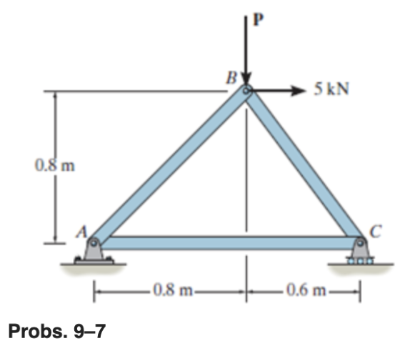
The truss is made of three A-36 steel members, each having across-sectional area of 400 mm2  . Determine the horizontal displacement of the roller C when P=8kN

Homework Answers
Draw the free body diagram of the truss.

Equate the sum of moments about A to zero.

Here,  is the vertical reaction at C.
Substitute  for
for  .
.

Equate the sum of horizontal forces to zero.

Here,  is the horizontal reaction at C.
Equate the sum of vertical forces to zero.

Here,  is the vertical reaction at A.
Substitute  for
for  and
and  for
for  .
.

Draw the free body diagram of the node C.

Equate the sum of vertical forces to zero.

Here,  is the force in the member BC.
Substitute  for
for  .
.

Equate the sum of horizontal forces to zero.

Here,  is the force in the member AC.
Substitute  for
for  .
.

Calculate the horizontal displacement of C.

Here,  is the length of the member AC,
  is the cross-sectional area of the rod, and
  is modulus of elasticity of the rod.
Substitute  for
for  ,
,  for
for  ,
,  for
for  , and
, and  for
for  .
.

Therefore, the horizontal displacement of C is  .
.
The truss shown in the figure is constructed from three aluminum alloy members, each having a...
 The truss shown in the figure is constructed from three aluminum alloy members, each having a cross-sectional area of A 800 mm2 and an elastic modulus of E 70 GPa. Assume that a 4.0 m, b 10.5 m, and c 5.0 m. Calculate the horizontal displacement of roller Bwhen the truss supports a load of P 14 kN B X a
The truss shown in the figure is constructed from three aluminum alloy members, each having a cross-sectional area of...
The truss shown in the figure is constructed from three aluminum alloy members, each having a cross-sectional area of A 800 mm2 and an elastic modulus of E 70 GPa. Assume that a 4.0 m, b 10.5 m, and c 5.0 m. Calculate the horizontal displacement of roller Bwhen the truss supports a load of P 14 kN B X a
The truss shown in the figure is constructed from three aluminum alloy members, each having a cross-sectional area of...
The truss is constructed from three aluminum alloy members, each having a cross-sectional area of A...
 The truss is constructed from three aluminum alloy members, each
having a cross-sectional area of A = 1350 mm2 and an elastic
modulus of E = 62 GPa. Assume a = 2.8 m, b = 9.0 m, and c = 5.5 m.
If the horizontal displacement of roller B must not exceed 5.0 mm,
calculate the maximum vertical load Pmax that can be supported by
the truss.
Chapter 5, Supplemental Question 008 The truss is constructed from three aluminum alloy...
The truss is constructed from three aluminum alloy members, each
having a cross-sectional area of A = 1350 mm2 and an elastic
modulus of E = 62 GPa. Assume a = 2.8 m, b = 9.0 m, and c = 5.5 m.
If the horizontal displacement of roller B must not exceed 5.0 mm,
calculate the maximum vertical load Pmax that can be supported by
the truss.
Chapter 5, Supplemental Question 008 The truss is constructed from three aluminum alloy...
The truss shown in the figure is constructed from three aluminum alloy members, each having a...
 The truss shown in the figure is constructed from three aluminum alloy members, each having a cross-sectional area of A 800 mm2 and an elastic modulus of E 70 GPa. Assume that a 4.0 m, b 10.5 m, and c 5.0 m. Calculate the horizontal displacement of roller Bwhen the truss supports a load of P 14 kN B X a
15 m B- Question 3: Each member of the truss shown is made of steel (E- 2 1 0 GPa ) and has a cro...
 15 m B- Question 3: Each member of the truss shown is made of steel (E- 2 1 0 GPa ) and has a cross-sectional area of A If you know that the joint E subjected to horizontal load 16-kN Determine: .The horizontal displacement of point E . The vertical displacement of point C. 400 mm2 0.8m 16 KN
15 m B- Question 3: Each member of the truss shown is made of steel (E- 2 1 0 GPa )...
15 m B- Question 3: Each member of the truss shown is made of steel (E- 2 1 0 GPa ) and has a cross-sectional area of A If you know that the joint E subjected to horizontal load 16-kN Determine: .The horizontal displacement of point E . The vertical displacement of point C. 400 mm2 0.8m 16 KN
15 m B- Question 3: Each member of the truss shown is made of steel (E- 2 1 0 GPa )...
The truss is constructed from three aluminum alloy members, each having a cross- sectional area of...
 The truss is constructed from three aluminum alloy members, each having a cross- sectional area of A = 850 mm2 and an elastic modulus of E = 63 GPa. Assume a = 3.4 m, b = 11.6 m, and c = 5.7 m. If the horizontal displacement of roller B must not exceed 3.6 mm, calculate the maximum vertical load Pmax that can be supported by the truss. Answer: Pmax = KN
All truss members are made with A36 steel having YP- 250MPa. If the truss is subjected...
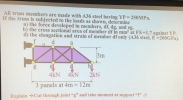 All truss members are made with A36 steel having YP- 250MPa. If the truss is subjected to the loads as shown, determine a) the force developed in members, df, dg, and eg. b) the cross sectional area of member df in mm2 at FS-1.7 against YP. d) the elongation and strain of member df only (A36 steel, E-200GPa). f d a 4kN 4kN 2kN 3 panels at 4m = 12m Explain → Cut through joint "g" and take moment at...
5. (20 points) The truss shown below supports horizontal forces of 6 kips at Joint G,...
 5. (20 points) The truss shown below supports horizontal forces of 6 kips at Joint G, 8 kips at Joint E, and 4 kips at Joint C. All truss members are made of steel (E 29,000 ksi). Each of the diagonal members (Members AD, DE, and EH) has a cross-sectional area of 1.2 in2. Each of the vertical members (Members AC, CE, EG, BD, DF and FH) has a cross-sectional area of 2.4 in Each of the horizontal members (Members...
Question 1 (25%) For the truss shown on figure 1, determine the horizontal displacement of point...
 Question 1 (25%) For the truss shown on figure 1, determine the horizontal displacement of point C when P 1000 N and P2 -0. Also, determine the vertical displacement of point F when P 0 et P2 1000 N. All members are prismatic and have the same elastic modulus fixed at 200 GPa. Area of each member is indicated in brackets (mm2). A (4000)B(400C (3000 (3000 2,75 D(5000 E(5000) Pi Figure 1
2. For the pin-jointed truss shown in Figure Q2.1 applied at node 4. The Young's modulus E(GPa) is the same for...
 2. For the pin-jointed truss shown in Figure Q2.1 applied at node 4. The Young's modulus E(GPa) is the same for the three truss vertical downward force P(kN) is a members. The cross sectional area of each of the truss members is indicated below and expressed in terms of a constant A. By using the stiffness method: (a) Compute the reduced stiffness matrix Kg [5 marks [10 marks (b) Calculate the global displacements of node 4 in terms of P,...
SAN4701 JAN/FE8 2017 QUESTION 1 1 is having a hinge support at 1 and a roller support at 2. (E - 200 GPa) for all the m...
 SAN4701 JAN/FE8 2017 QUESTION 1 1 is having a hinge support at 1 and a roller support at 2. (E - 200 GPa) for all the members and the members 1, d 3 have their cross sectional areas as 4000 mm2, 4000 mm2 and 6000 mm2 The truss shown in Figure Assuming that E is constant respectively, use the matrix stiffness method to determine the following Number of degrees of freedom. a. (15) b. Structure stiffness matrıx. (10) c Member...
 The truss shown in the figure is constructed from three aluminum alloy members, each having a cross-sectional area of A 800 mm2 and an elastic modulus of E 70 GPa. Assume that a 4.0 m, b 10.5 m, and c 5.0 m. Calculate the horizontal displacement of roller Bwhen the truss supports a load of P 14 kN B X a
The truss shown in the figure is constructed from three aluminum alloy members, each having a cross-sectional area of...
The truss shown in the figure is constructed from three aluminum alloy members, each having a cross-sectional area of A 800 mm2 and an elastic modulus of E 70 GPa. Assume that a 4.0 m, b 10.5 m, and c 5.0 m. Calculate the horizontal displacement of roller Bwhen the truss supports a load of P 14 kN B X a
The truss shown in the figure is constructed from three aluminum alloy members, each having a cross-sectional area of...
 The truss is constructed from three aluminum alloy members, each
having a cross-sectional area of A = 1350 mm2 and an elastic
modulus of E = 62 GPa. Assume a = 2.8 m, b = 9.0 m, and c = 5.5 m.
If the horizontal displacement of roller B must not exceed 5.0 mm,
calculate the maximum vertical load Pmax that can be supported by
the truss.
Chapter 5, Supplemental Question 008 The truss is constructed from three aluminum alloy...
The truss is constructed from three aluminum alloy members, each
having a cross-sectional area of A = 1350 mm2 and an elastic
modulus of E = 62 GPa. Assume a = 2.8 m, b = 9.0 m, and c = 5.5 m.
If the horizontal displacement of roller B must not exceed 5.0 mm,
calculate the maximum vertical load Pmax that can be supported by
the truss.
Chapter 5, Supplemental Question 008 The truss is constructed from three aluminum alloy...
 The truss shown in the figure is constructed from three aluminum alloy members, each having a cross-sectional area of A 800 mm2 and an elastic modulus of E 70 GPa. Assume that a 4.0 m, b 10.5 m, and c 5.0 m. Calculate the horizontal displacement of roller Bwhen the truss supports a load of P 14 kN B X a
 15 m B- Question 3: Each member of the truss shown is made of steel (E- 2 1 0 GPa ) and has a cross-sectional area of A If you know that the joint E subjected to horizontal load 16-kN Determine: .The horizontal displacement of point E . The vertical displacement of point C. 400 mm2 0.8m 16 KN
15 m B- Question 3: Each member of the truss shown is made of steel (E- 2 1 0 GPa )...
15 m B- Question 3: Each member of the truss shown is made of steel (E- 2 1 0 GPa ) and has a cross-sectional area of A If you know that the joint E subjected to horizontal load 16-kN Determine: .The horizontal displacement of point E . The vertical displacement of point C. 400 mm2 0.8m 16 KN
15 m B- Question 3: Each member of the truss shown is made of steel (E- 2 1 0 GPa )...
 The truss is constructed from three aluminum alloy members, each having a cross- sectional area of A = 850 mm2 and an elastic modulus of E = 63 GPa. Assume a = 3.4 m, b = 11.6 m, and c = 5.7 m. If the horizontal displacement of roller B must not exceed 3.6 mm, calculate the maximum vertical load Pmax that can be supported by the truss. Answer: Pmax = KN
 All truss members are made with A36 steel having YP- 250MPa. If the truss is subjected to the loads as shown, determine a) the force developed in members, df, dg, and eg. b) the cross sectional area of member df in mm2 at FS-1.7 against YP. d) the elongation and strain of member df only (A36 steel, E-200GPa). f d a 4kN 4kN 2kN 3 panels at 4m = 12m Explain → Cut through joint "g" and take moment at...
 5. (20 points) The truss shown below supports horizontal forces of 6 kips at Joint G, 8 kips at Joint E, and 4 kips at Joint C. All truss members are made of steel (E 29,000 ksi). Each of the diagonal members (Members AD, DE, and EH) has a cross-sectional area of 1.2 in2. Each of the vertical members (Members AC, CE, EG, BD, DF and FH) has a cross-sectional area of 2.4 in Each of the horizontal members (Members...
 Question 1 (25%) For the truss shown on figure 1, determine the horizontal displacement of point C when P 1000 N and P2 -0. Also, determine the vertical displacement of point F when P 0 et P2 1000 N. All members are prismatic and have the same elastic modulus fixed at 200 GPa. Area of each member is indicated in brackets (mm2). A (4000)B(400C (3000 (3000 2,75 D(5000 E(5000) Pi Figure 1
 2. For the pin-jointed truss shown in Figure Q2.1 applied at node 4. The Young's modulus E(GPa) is the same for the three truss vertical downward force P(kN) is a members. The cross sectional area of each of the truss members is indicated below and expressed in terms of a constant A. By using the stiffness method: (a) Compute the reduced stiffness matrix Kg [5 marks [10 marks (b) Calculate the global displacements of node 4 in terms of P,...
 SAN4701 JAN/FE8 2017 QUESTION 1 1 is having a hinge support at 1 and a roller support at 2. (E - 200 GPa) for all the members and the members 1, d 3 have their cross sectional areas as 4000 mm2, 4000 mm2 and 6000 mm2 The truss shown in Figure Assuming that E is constant respectively, use the matrix stiffness method to determine the following Number of degrees of freedom. a. (15) b. Structure stiffness matrıx. (10) c Member...
Most questions answered within 3 hours.
-
Where is the error in this code sequence?
String s1 = "Hello";
String s2 = "ello";...
asked 11 months ago -
Financial data for Joel de Paris, Inc., for last year
follow:
Joel de Paris, Inc.
Balance...
asked 11 months ago -
Consider this reaction:
Al2(SO4)3 (aq)+ BaCl3
(aq) Al2Cl6 (aq)- +
3BaSO4(s) . What is the...
asked 11 months ago -
Suppose that Savneet is considering increasing her
recent random sample from 20 car rentals to 40...
asked 11 months ago -
Trucks arrive at an unloading terminal at an average rate of 120
per hour.
Trucks arrive...
asked 11 months ago -
Why are methanol and ethanol completely soluble in water while
octanol is not very little soluble....
asked 11 months ago -
A facilities manager at a university reads in a research report
that the mean amount of...
asked 11 months ago -
When the CuSO4 is rehydrated by adding water to the anhydrous
compound, is this an endothermic...
asked 11 months ago -
A ray of sunlight is passing from diamond into crown glass; the
angle of incidence is...
asked 11 months ago -
A block of mass 0.249 kg is placed on top of a light, vertical
spring of...
asked 11 months ago -
how do the kidneys compensate in the presences of acidosis
a) trigger hyperventilate
b) reserve acid...
asked 11 months ago -
Question 501 pts
The rental rate of capital to the firm increases. Which of the
following...
asked 11 months ago