Tests at two terminals of a linear network produce the following ‐ With the terminals shorted...
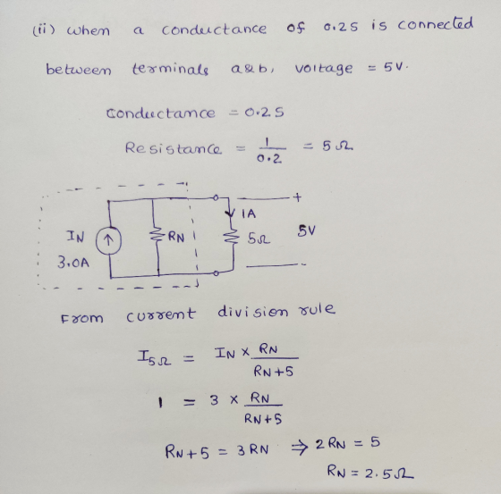
Tests at two terminals of a linear network produce the following ‐ With the terminals shorted the current in the short circuit is 3.0A ‐ With a conductance of 0.2 S connected to the terminals the voltage between the terminals is 5 V The linear network may be replaced by current source amperes in parallel with a conductance (S) of most
Current – Conductance
a)1.0 - 0.2
b) 3.0 - 0.4
c) 2.0 - 0.6
d) 3.0 - 0.6
Homework Answers
Page 1

Page 2

Page 3
Page 4

Here, initially linear network is represented with current source in parallel with resistance. This representation is called Norton circuit representation. After knowing I_N and R_N values, circuit got converted into current-conductance form.
Add Answer to:
Tests at two terminals of a linear network produce the following
‐ With the terminals shorted...
Thevenin's Theorem. "Any two-terminal, linear bilateral DC network can be replaced by an equivalent circuit consisting...
 Thevenin's Theorem. "Any two-terminal, linear bilateral DC network can be replaced by an equivalent circuit consisting of a voltage source and a series resistor."This means that a circuit such as the one in Figure 1 can be replaced by a power supply and a series resistor, allowing for a quicker analysis of changes in load resistance,(RO) R3 Figure 1 Some of the advantages offered by this theorem are: • It allows the determination of any given voltage or current in...
2. Consider an N-channel MOSFET circuit where the gate and drain terminals are shorted to- gether...
 Please help, and explain as much as possible. Thank
you!
2. Consider an N-channel MOSFET circuit where the gate and drain terminals are shorted to- gether2 as shown in Figre 2. Assume that the MOSFET has trans-conductance parameter of gm = 0.5mA/V and the threshold voltage of 0.7V (a) Identify in which region the n-channel MOSFET is operating (Triode region or Saturation region)? (b) Write MATLAB code to compute the drain current for the following gate-to-source voltage, Vcs Ves-VDs 0,1,2,3,4,5,6,7...
Please help, and explain as much as possible. Thank
you!
2. Consider an N-channel MOSFET circuit where the gate and drain terminals are shorted to- gether2 as shown in Figre 2. Assume that the MOSFET has trans-conductance parameter of gm = 0.5mA/V and the threshold voltage of 0.7V (a) Identify in which region the n-channel MOSFET is operating (Triode region or Saturation region)? (b) Write MATLAB code to compute the drain current for the following gate-to-source voltage, Vcs Ves-VDs 0,1,2,3,4,5,6,7...
A Review Constants Part E - Determine the equivalent capacitance across terminals a and b Learning...
 A Review Constants Part E - Determine the equivalent capacitance across terminals a and b Learning Goal: To reduce series-parallel combinations of inductors or capacitors to an equivalent inductance or capacitance. Inductors in series and parallel combine like resistors in series and parallel. It is possible to use Kirchhoff's current law to find the current through the equivalent inductance. Moreover, capacitors in series combine like resistors in parallel and vice versa. It is possible to use Kirchhoff's voltage law to...
M Review Constants Part A - Determine the equivalent inductance to the right of terminals b...
 M Review Constants Part A - Determine the equivalent inductance to the right of terminals b and e, including L4 Learning Goal: To reduce series-parallel combinations of inductors or capacitors to an equivalent inductance or capacitance. Inductors in series and parallel combine like resistors in series and parallel. It is possible to use Kirchhoffs current law to find the current through the equivalent inductance. Moreover, capacitors in series combine like resistors in parallel and vice versa. It is possible to...
If the total current through the circuit is / 3.0 A, what is the current through the 12 Ω resistor?
 Three resistors of values 2 Ω, 6 Ω and 12 Ω are connected across a DC voltage source as shown in Figure 21-12. If the total current through the circuit is / 3.0 A, what is the current through the 12 Ω resistor? 0.3 A 0.4 A 0.2 A 0.6 A 0.5 A
Q8. The following data are obtained when open circuit and short circuit tests are performed on...
 Q8. The following data are obtained when open circuit and short circuit tests are performed on a single phase, 50 kVA, 2400/240 Volt 50 HZ distribution transformer. VOLTAGE(volts)CURRENT (amperes) POWER (watts) 213 Measurement in low voltage side with high voltage winding open Measurement on high voltage side with low voltage winding shorted 240 5.97 60 20.8 750 (a) Neglecting the series impedance, determine the exciting admittance referred to the high voltage side. (b) Neglecting the exciting admittance, determine the equivalent...
To practice Problem-Solving Strategy 26.1 Resistors in Series and Parallel. Two bulbs are connected in parallel...
To practice Problem-Solving Strategy 26.1 Resistors in Series and Parallel. Two bulbs are connected in parallel across a source of emf EEEMF = 12.0 VV with a negligible internal resistance. One bulb has a resistance of 3.0 ΩΩ , and the other is 3.0 ΩΩ . A resistor RRR is connected in the circuit in series with the two bulbs. What value of RRR should be chosen in order to supply each bulb with a voltage of 2.4 VV ?...
Question 1. (a) Consider the waveform below that has a period of T of 0.04 seconds....
 Question 1. (a) Consider the waveform below that has a period of T of 0.04 seconds. What is the rms voltage of this waveform? V(t) 15 V 0.01 s 0.02 s T=0.04s (b) The figure below shows a network of resistances and reactances having values as shown connected to a voltage source with a voltage of (50+0j) volts rms and an angular frequency of 1000 rad/s. А. 32 3 mH V 52 200 uF 2 mH 1 mH (i) Redraw...
Build an Op-Amp Circuit Network. Note you only have a power source of 5V available. You...
Build an Op-Amp Circuit Network. Note you only have a power source of 5V available. You have a voltage signal that latches at a constant 1.5V. Create a difference circuit to produce an output voltage of 2V. Put P/Ns and element values in your design. Show your work. From part a)’s output voltage, assign that now as a reference voltage (Vref) to compare to an analog sensor signal (Vin) that can range between 0V – 5V. Make sure your circuit...
only write a conclusion/lesson learnt based off the experiment (iry After performing this experiment, you will...
 only write a conclusion/lesson learnt based off the
experiment
(iry After performing this experiment, you will be able to: I. Change a linear network containing several resistors into an nt Thevenin circuit. circuit by comparing the 2. Prove the equivalency of the network in objective 1 with the effects of various load resistors. Materials Needed: Resistors: One 150 Ω, one 270 Ω, one 470 Ω, one 560 Ω, one 680 Ω, one 820 Ω One 1 k2 potentiometer Summary of...
only write a conclusion/lesson learnt based off the
experiment
(iry After performing this experiment, you will be able to: I. Change a linear network containing several resistors into an nt Thevenin circuit. circuit by comparing the 2. Prove the equivalency of the network in objective 1 with the effects of various load resistors. Materials Needed: Resistors: One 150 Ω, one 270 Ω, one 470 Ω, one 560 Ω, one 680 Ω, one 820 Ω One 1 k2 potentiometer Summary of...
 Thevenin's Theorem. "Any two-terminal, linear bilateral DC network can be replaced by an equivalent circuit consisting of a voltage source and a series resistor."This means that a circuit such as the one in Figure 1 can be replaced by a power supply and a series resistor, allowing for a quicker analysis of changes in load resistance,(RO) R3 Figure 1 Some of the advantages offered by this theorem are: • It allows the determination of any given voltage or current in...
 Please help, and explain as much as possible. Thank
you!
2. Consider an N-channel MOSFET circuit where the gate and drain terminals are shorted to- gether2 as shown in Figre 2. Assume that the MOSFET has trans-conductance parameter of gm = 0.5mA/V and the threshold voltage of 0.7V (a) Identify in which region the n-channel MOSFET is operating (Triode region or Saturation region)? (b) Write MATLAB code to compute the drain current for the following gate-to-source voltage, Vcs Ves-VDs 0,1,2,3,4,5,6,7...
Please help, and explain as much as possible. Thank
you!
2. Consider an N-channel MOSFET circuit where the gate and drain terminals are shorted to- gether2 as shown in Figre 2. Assume that the MOSFET has trans-conductance parameter of gm = 0.5mA/V and the threshold voltage of 0.7V (a) Identify in which region the n-channel MOSFET is operating (Triode region or Saturation region)? (b) Write MATLAB code to compute the drain current for the following gate-to-source voltage, Vcs Ves-VDs 0,1,2,3,4,5,6,7...
 A Review Constants Part E - Determine the equivalent capacitance across terminals a and b Learning Goal: To reduce series-parallel combinations of inductors or capacitors to an equivalent inductance or capacitance. Inductors in series and parallel combine like resistors in series and parallel. It is possible to use Kirchhoff's current law to find the current through the equivalent inductance. Moreover, capacitors in series combine like resistors in parallel and vice versa. It is possible to use Kirchhoff's voltage law to...
 M Review Constants Part A - Determine the equivalent inductance to the right of terminals b and e, including L4 Learning Goal: To reduce series-parallel combinations of inductors or capacitors to an equivalent inductance or capacitance. Inductors in series and parallel combine like resistors in series and parallel. It is possible to use Kirchhoffs current law to find the current through the equivalent inductance. Moreover, capacitors in series combine like resistors in parallel and vice versa. It is possible to...
 Three resistors of values 2 Ω, 6 Ω and 12 Ω are connected across a DC voltage source as shown in Figure 21-12. If the total current through the circuit is / 3.0 A, what is the current through the 12 Ω resistor? 0.3 A 0.4 A 0.2 A 0.6 A 0.5 A
 Q8. The following data are obtained when open circuit and short circuit tests are performed on a single phase, 50 kVA, 2400/240 Volt 50 HZ distribution transformer. VOLTAGE(volts)CURRENT (amperes) POWER (watts) 213 Measurement in low voltage side with high voltage winding open Measurement on high voltage side with low voltage winding shorted 240 5.97 60 20.8 750 (a) Neglecting the series impedance, determine the exciting admittance referred to the high voltage side. (b) Neglecting the exciting admittance, determine the equivalent...
 Question 1. (a) Consider the waveform below that has a period of T of 0.04 seconds. What is the rms voltage of this waveform? V(t) 15 V 0.01 s 0.02 s T=0.04s (b) The figure below shows a network of resistances and reactances having values as shown connected to a voltage source with a voltage of (50+0j) volts rms and an angular frequency of 1000 rad/s. А. 32 3 mH V 52 200 uF 2 mH 1 mH (i) Redraw...
 only write a conclusion/lesson learnt based off the
experiment
(iry After performing this experiment, you will be able to: I. Change a linear network containing several resistors into an nt Thevenin circuit. circuit by comparing the 2. Prove the equivalency of the network in objective 1 with the effects of various load resistors. Materials Needed: Resistors: One 150 Ω, one 270 Ω, one 470 Ω, one 560 Ω, one 680 Ω, one 820 Ω One 1 k2 potentiometer Summary of...
only write a conclusion/lesson learnt based off the
experiment
(iry After performing this experiment, you will be able to: I. Change a linear network containing several resistors into an nt Thevenin circuit. circuit by comparing the 2. Prove the equivalency of the network in objective 1 with the effects of various load resistors. Materials Needed: Resistors: One 150 Ω, one 270 Ω, one 470 Ω, one 560 Ω, one 680 Ω, one 820 Ω One 1 k2 potentiometer Summary of...
Most questions answered within 3 hours.
-
Where is the error in this code sequence?
String s1 = "Hello";
String s2 = "ello";...
asked 10 months ago -
Financial data for Joel de Paris, Inc., for last year
follow:
Joel de Paris, Inc.
Balance...
asked 10 months ago -
Consider this reaction:
Al2(SO4)3 (aq)+ BaCl3
(aq) Al2Cl6 (aq)- +
3BaSO4(s) . What is the...
asked 10 months ago -
Suppose that Savneet is considering increasing her
recent random sample from 20 car rentals to 40...
asked 10 months ago -
Trucks arrive at an unloading terminal at an average rate of 120
per hour.
Trucks arrive...
asked 10 months ago -
Why are methanol and ethanol completely soluble in water while
octanol is not very little soluble....
asked 10 months ago -
A facilities manager at a university reads in a research report
that the mean amount of...
asked 10 months ago -
When the CuSO4 is rehydrated by adding water to the anhydrous
compound, is this an endothermic...
asked 10 months ago -
A ray of sunlight is passing from diamond into crown glass; the
angle of incidence is...
asked 10 months ago -
A block of mass 0.249 kg is placed on top of a light, vertical
spring of...
asked 10 months ago -
how do the kidneys compensate in the presences of acidosis
a) trigger hyperventilate
b) reserve acid...
asked 10 months ago -
Question 501 pts
The rental rate of capital to the firm increases. Which of the
following...
asked 10 months ago