Please solve 2.5. It requires material from 2.4. 2.5 Solve Problem 2.4 assuming that the line...
Please solve 2.5. It requires material from 2.4.
2.5 Solve Problem 2.4 assuming that the line impedance is 50∠26° per phase.
2.4 Assume that the impedance of a power line connecting buses 1 and 2 is 50∠70° Ω, and that the bus voltages are 7560∠− 10° and 7200∠0° V per phase, respectively. Determine the following:
(a) The real power per phase that is being transmitted from bus 1 to bus 2
(b) The reactive power per phase that is being transmitted from bus 1 to bus 2
(c) The complex power per phase that is being
transmitted
Homework Answers
Page 1

Page 2
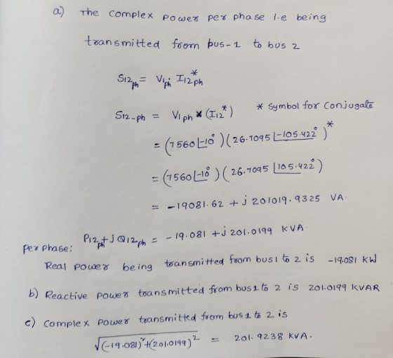
Here, first current flowing in line is calculated first, then complex power flowing from bus 1 to bus 2 is calculated. From where, active power and reactive power flows per phase from bus 1 to bus 2 are calculated.
Here, S_12=-19.081+j*201.0199 KVA. Complex power flow is represented in magnitude form. If it is needed in polar form then S_12=201.9238<95,42 degrees KVA.
Add Answer to:
Please solve 2.5. It requires material from
2.4.
2.5 Solve Problem 2.4 assuming that the line...
2.4 Assume that the impedance of a power line connecting buses 1 and 2 is 50270°...
 2.4 Assume that the impedance of a power line connecting buses 1 and 2 is 50270° 2, and that the bus voltages are 7560/-10° and 7200L0° V per phase, respectively. Determine the following: (a) The real power per phase that is being transmitted from bus 1 to bus 2 (b) The reactive power per phase that is being transmitted from bus 1 to bus2
A three-phase line, which has an impedance of (2 + j4) Ω per phase, feeds two...
A three-phase line, which has an impedance of (2 + j4) Ω per phase, feeds two balanced three-phase loads that are connected in parallel. One of the loads is Y- connected with an impedance of (30 + j40) Ω per phase, and the other is delta- connected with an impedance of (60 + j45) Ω per phase. The line is energized at the sending end from a 60-Hz, three phase, balanced voltage source of 120√3 V (rms, line- to-line). Determine...
The impedance of a three-phase line is 0.3 + j 2.4 per phase. The line feeds...
The impedance of a three-phase line is 0.3 + j 2.4 per phase. The line feeds two balanced three- phase loads connected in parallel. The first load takes 600 kVA at 0.7 p.f. lagging. The second takes 150 kW at unity power factor. The line to line voltage at the load end of the line is 3810.5 V. Find a) The magnitude of the line voltage at the source end of the line. b) The total active and reactive power...
Question: A three-phase line has an impedance of 1 + j2 Ω per phase. The line...
Question: A three-phase line has an impedance of 1 + j2 Ω per phase. The line feeds two balanced three-phase loads that are connected in parallel. The first load is Y-connected and has an impedance of 20+j40 Ω per phase. The second load is ∆-connected and has an impedance of 30-j60 Ω per phase. The line-to-line voltage at the load end of the line is 415V. Taking the phase voltage Va as reference, determine: a) The total current per phase...
Problem 1 A 3-phase, Y/Y system is supplied from a 450 V (line). The load impedance...
 Problem 1 A 3-phase, Y/Y system is supplied from a 450 V (line). The load impedance is 6tj 10 Ω/phase. Please do the following a) Draw the single-phase equivalent circuit of phase A b) Find the magnitude of all line and phase currents c) Find the real power delivered to the load d) Find the reactive power delivered to the load e) Find the apparent power delivered to the load f) Find the power factor of the load
Please answer ALL PARTS of this question. 1) Calculate the three line currents . Enter its...
 Please answer ALL PARTS of this question.
1) Calculate the three line
currents . Enter its magnitude in A
2) Calculate the three line currents . Enter its phase angle in degrees
3) Calculate the phase voltage at terminal of the load. Enter its
magnitude in V
4) Calculate the phase voltage at terminal of the load. Enter its phase
angle in degrees
5) Calculate the line voltage at the load. Enter its magnitude in V
6) Calculate the line...
Please answer ALL PARTS of this question.
1) Calculate the three line
currents . Enter its magnitude in A
2) Calculate the three line currents . Enter its phase angle in degrees
3) Calculate the phase voltage at terminal of the load. Enter its
magnitude in V
4) Calculate the phase voltage at terminal of the load. Enter its phase
angle in degrees
5) Calculate the line voltage at the load. Enter its magnitude in V
6) Calculate the line...
1. In a three-phase balanced wye-wye system, the source is an abc-positive sequence set of voltag...
 1. In a three-phase balanced wye-wye system, the source is an abc-positive sequence set of voltages with Van- 120 20 Vrms. The per phase impedance of the load is 5 +j62. If the line impedance per phase is 0 Ω, find the line currents, the line to line voltages at the source, and the line to line voltages at the load 120 20 Vms 2. In a three-phase balanced wye-wye system, the source is an abc-sequence set of voltages with...
solve no: 3.14 , 3.16, 3.19 please show each step and solve for beginners 120 Power...
 solve no: 3.14 , 3.16, 3.19
please show each step and solve for beginners
120 Power System Analysis 3.12. A single-phase system similar to that shown in Figure 3.11 has two transformers A-B a B-C connected by a line B feeding a load at the receiving end C. The ratings and parame ter values of the components are 500 V/1.5 kV, 9.6 kVA. leakage reactance 5 % 1.2 kV/120 V, 7.2 kVA, leakage reactance 4 % series impedance (0.5 +...
solve no: 3.14 , 3.16, 3.19
please show each step and solve for beginners
120 Power System Analysis 3.12. A single-phase system similar to that shown in Figure 3.11 has two transformers A-B a B-C connected by a line B feeding a load at the receiving end C. The ratings and parame ter values of the components are 500 V/1.5 kV, 9.6 kVA. leakage reactance 5 % 1.2 kV/120 V, 7.2 kVA, leakage reactance 4 % series impedance (0.5 +...
The single line diagram of a power network is shown in the figure. Bus#1 is a slack bus. The sche...
 The single line diagram of a power network is shown in the figure. Bus#1 is a slack bus. The scheduled powers for bus#2 and bus#3 are given. The impedances shown in the figure are all in per-unit considering a power base of 100 MVA. 30 400 MW 320 MVAr Slack V-1400.0125 jo.os 3 300 MW 270 MVAr A. Use the Gauss Seidel technique to determine voltages at bus#2 & bus#3. (Start with an initial guess 140 for both buses). [Only...
The one line diagram of a three-phase power system is shown in Fig.8. Impedances are marked...
 The one line diagram of a three-phase power system is shown in
Fig.8. Impedances are marked in per unit on a 100 MW, 400 kV base.
The Load at Bus 2 is S2 = 15.93 MW - j33.4Mvar, and at Bus 3 is S3
= 77 MW + j14 Mvar. It is required to hold the voltage at Bus 3 at
400 kV, Angle 0 degs. Working in per unit, determine the voltages
at Buses 2 and 1.
Q8: The...
The one line diagram of a three-phase power system is shown in
Fig.8. Impedances are marked in per unit on a 100 MW, 400 kV base.
The Load at Bus 2 is S2 = 15.93 MW - j33.4Mvar, and at Bus 3 is S3
= 77 MW + j14 Mvar. It is required to hold the voltage at Bus 3 at
400 kV, Angle 0 degs. Working in per unit, determine the voltages
at Buses 2 and 1.
Q8: The...
 2.4 Assume that the impedance of a power line connecting buses 1 and 2 is 50270° 2, and that the bus voltages are 7560/-10° and 7200L0° V per phase, respectively. Determine the following: (a) The real power per phase that is being transmitted from bus 1 to bus 2 (b) The reactive power per phase that is being transmitted from bus 1 to bus2
 Problem 1 A 3-phase, Y/Y system is supplied from a 450 V (line). The load impedance is 6tj 10 Ω/phase. Please do the following a) Draw the single-phase equivalent circuit of phase A b) Find the magnitude of all line and phase currents c) Find the real power delivered to the load d) Find the reactive power delivered to the load e) Find the apparent power delivered to the load f) Find the power factor of the load
 Please answer ALL PARTS of this question.
1) Calculate the three line
currents . Enter its magnitude in A
2) Calculate the three line currents . Enter its phase angle in degrees
3) Calculate the phase voltage at terminal of the load. Enter its
magnitude in V
4) Calculate the phase voltage at terminal of the load. Enter its phase
angle in degrees
5) Calculate the line voltage at the load. Enter its magnitude in V
6) Calculate the line...
Please answer ALL PARTS of this question.
1) Calculate the three line
currents . Enter its magnitude in A
2) Calculate the three line currents . Enter its phase angle in degrees
3) Calculate the phase voltage at terminal of the load. Enter its
magnitude in V
4) Calculate the phase voltage at terminal of the load. Enter its phase
angle in degrees
5) Calculate the line voltage at the load. Enter its magnitude in V
6) Calculate the line...
 1. In a three-phase balanced wye-wye system, the source is an abc-positive sequence set of voltages with Van- 120 20 Vrms. The per phase impedance of the load is 5 +j62. If the line impedance per phase is 0 Ω, find the line currents, the line to line voltages at the source, and the line to line voltages at the load 120 20 Vms 2. In a three-phase balanced wye-wye system, the source is an abc-sequence set of voltages with...
 solve no: 3.14 , 3.16, 3.19
please show each step and solve for beginners
120 Power System Analysis 3.12. A single-phase system similar to that shown in Figure 3.11 has two transformers A-B a B-C connected by a line B feeding a load at the receiving end C. The ratings and parame ter values of the components are 500 V/1.5 kV, 9.6 kVA. leakage reactance 5 % 1.2 kV/120 V, 7.2 kVA, leakage reactance 4 % series impedance (0.5 +...
solve no: 3.14 , 3.16, 3.19
please show each step and solve for beginners
120 Power System Analysis 3.12. A single-phase system similar to that shown in Figure 3.11 has two transformers A-B a B-C connected by a line B feeding a load at the receiving end C. The ratings and parame ter values of the components are 500 V/1.5 kV, 9.6 kVA. leakage reactance 5 % 1.2 kV/120 V, 7.2 kVA, leakage reactance 4 % series impedance (0.5 +...
 The single line diagram of a power network is shown in the figure. Bus#1 is a slack bus. The scheduled powers for bus#2 and bus#3 are given. The impedances shown in the figure are all in per-unit considering a power base of 100 MVA. 30 400 MW 320 MVAr Slack V-1400.0125 jo.os 3 300 MW 270 MVAr A. Use the Gauss Seidel technique to determine voltages at bus#2 & bus#3. (Start with an initial guess 140 for both buses). [Only...
 The one line diagram of a three-phase power system is shown in
Fig.8. Impedances are marked in per unit on a 100 MW, 400 kV base.
The Load at Bus 2 is S2 = 15.93 MW - j33.4Mvar, and at Bus 3 is S3
= 77 MW + j14 Mvar. It is required to hold the voltage at Bus 3 at
400 kV, Angle 0 degs. Working in per unit, determine the voltages
at Buses 2 and 1.
Q8: The...
The one line diagram of a three-phase power system is shown in
Fig.8. Impedances are marked in per unit on a 100 MW, 400 kV base.
The Load at Bus 2 is S2 = 15.93 MW - j33.4Mvar, and at Bus 3 is S3
= 77 MW + j14 Mvar. It is required to hold the voltage at Bus 3 at
400 kV, Angle 0 degs. Working in per unit, determine the voltages
at Buses 2 and 1.
Q8: The...
Most questions answered within 3 hours.
-
Where is the error in this code sequence?
String s1 = "Hello";
String s2 = "ello";...
asked 10 months ago -
Financial data for Joel de Paris, Inc., for last year
follow:
Joel de Paris, Inc.
Balance...
asked 10 months ago -
Consider this reaction:
Al2(SO4)3 (aq)+ BaCl3
(aq) Al2Cl6 (aq)- +
3BaSO4(s) . What is the...
asked 10 months ago -
Suppose that Savneet is considering increasing her
recent random sample from 20 car rentals to 40...
asked 10 months ago -
Trucks arrive at an unloading terminal at an average rate of 120
per hour.
Trucks arrive...
asked 10 months ago -
Why are methanol and ethanol completely soluble in water while
octanol is not very little soluble....
asked 10 months ago -
A facilities manager at a university reads in a research report
that the mean amount of...
asked 10 months ago -
When the CuSO4 is rehydrated by adding water to the anhydrous
compound, is this an endothermic...
asked 10 months ago -
A ray of sunlight is passing from diamond into crown glass; the
angle of incidence is...
asked 10 months ago -
A block of mass 0.249 kg is placed on top of a light, vertical
spring of...
asked 10 months ago -
how do the kidneys compensate in the presences of acidosis
a) trigger hyperventilate
b) reserve acid...
asked 10 months ago -
Question 501 pts
The rental rate of capital to the firm increases. Which of the
following...
asked 10 months ago