Exercise 1 Electric Fields In this exercise, you will use a digital multimeter to collect voltage...
Exercise 1 Electric Fields In this exercise, you will use a digital multimeter to collect voltage data to graph electric fields. Procedure Place the sheet of graph paper on a table and center the clear tray over the grid. Attach the end of each jumper cable to a metal nut by clamping the free alligator clip onto it as shown in Figure 4. The figure is a photo of an alligator clip attached to a metal nut. It is attached so that one jaw of the clip is inside the nut, against the threads, and the other jaw is on the outside. Figure 4. Attaching the alligator clip to the metal nut. Place the two metal nut conductors in opposite ends of the clear tray. They should be approximately centered and about 2.5 cm away from the ends of the tray. Position the battery holder with a 1.5V battery outside of and slightly away from the tray so it cannot get wet. Attach the jumper cables from the two conductors to the battery holder, one to the positive terminal and the other to the negative terminal. Fill the tray with sufficient water to just barely cover the conductors. Set your DMM to measure voltage by moving the dial to DCV, and its range to a voltage equal to or higher than that of the 1.5V battery. Attach the negative black lead from the DMM to the negative terminal of the battery holder. Attach a jumper cable to the positive red lead that comes from the DMM. To the other end of the jumper cable attach the washer. See Figure 5. The figure is a photo of the experiment setup. The two nuts are positioned in the clear tray, each connected to opposite terminals of the battery holder. One lead from the digital multimeter is connected to the metal washer, and the other lead is connected to the negative terminal of the battery holder. Figure 5. Experimental setup. With the DMM's positive red lead, touch each of the conductors in the tray and record your findings. Touching the negative conductor in the tray should result in a zero volt reading, Touching the positive conductor should result in a reading that is the same as the battery output, and Touching a distance halfway between the conductors should record a voltage equal to approximately one-half the voltage of the battery. If it does not, stir a few grains of salt into the water in the tray. Using the second sheet of graph paper, draw the conductors' locations and label them with the voltage readings of your voltmeter. Place the positive red lead of the DMM in the water again and note the voltage reading. Move the lead around in such a way that the voltage reading is kept at the same value. How far does this path go? Sketch this pattern on your graph paper and label the line with the voltage you chose. Move the positive lead along additional voltage value paths and similarly sketch their patterns on the graph paper until you have well mapped out the area between and around the conductors. With a color pen or pencil draw a point any place on your map to represent a moveable positive charge. Predict the path it would take by drawing a line with your colored pen or pencil. See Figure 6. The figure is a sample graph of experimental results. It shows a 4.5 V trace encircling the +5V electrode. The 4.0 V, 3.5 V, and 3.0 V traces form arcs which curve around the +5V electrode. The 2.5 V, 2.0 V, and 1.5 V traces form arcs which curve around the 0V electrode. The 1.0 V trace encircles the 0V electrode. Figure 6. Sample graph of experimental results. Note: Your results will look different from the sample since you will use a rectangular dish, place your conductors in different positions, and use a 1.5V battery, but it still illustrates the concept of electric field mapping. Take a photo of the graph. Upload the image into Graph 1. Optional: If time permits, repeat this experiment with differently shaped conductors and compare their electric field maps.
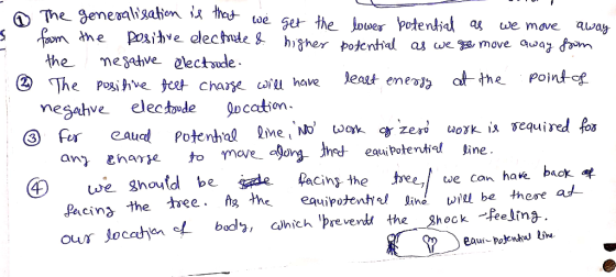
1. What generalizations can you make from this exploration?
2. Where would a positive test charge have the least potential energy?
3. How much energy must you add to the system to move one electron 1 m in a direction along one of the equal potential lines?
4. If lightning strikes a tree 20 m away, would it be better to stand facing the tree, your back to the tree, or your side to the tree? Assume your feet are a comfortable shoulder width apart. Explain your answer.
Homework Answers
 Thank you. Please like the
answer.ASAP. I made all the representations in diagram at below
point. Thank you.
Thank you. Please like the
answer.ASAP. I made all the representations in diagram at below
point. Thank you.
Add Answer to:
Exercise 1 Electric Fields In this exercise, you will use a
digital multimeter to collect voltage...
Page 1 and 2 are instructions. Please help me solve K for page 3 and page...
 Page 1 and 2 are instructions. Please help me solve K for page 3
and page 4 and please check the other work on Page 3.
Thanyou very much. Will Rate!
CHM 112 Electrochemical Cells and Thermodynamics Section A. Constructing a Small-Scale Electrochemical Cell Woodbridge Campus Objective To construct a small-scale electrochemical cell using a redox system, to measure the cell potential and derive thermodynamic quantities. Procedures 1. Connect the red and black alligator clips to the multimeter to read...
Page 1 and 2 are instructions. Please help me solve K for page 3
and page 4 and please check the other work on Page 3.
Thanyou very much. Will Rate!
CHM 112 Electrochemical Cells and Thermodynamics Section A. Constructing a Small-Scale Electrochemical Cell Woodbridge Campus Objective To construct a small-scale electrochemical cell using a redox system, to measure the cell potential and derive thermodynamic quantities. Procedures 1. Connect the red and black alligator clips to the multimeter to read...
5. What was the purpose of the NaNO3 solution in this experiment? 6. Could a solution...
 5. What was the purpose of the NaNO3 solution in this experiment? 6. Could a solution of NaCl be used instead of NaNO3? 7. What was the purpose of FeSO4 solution in this experiment? 8. Could a solution of FeCl, be used instead of FeSO4? 9. Could a solution of NaSO4 be used instead of FeSO4? 10. Calculate the standard cell potential for the spontaneous redox reaction between a Pb(s)/Pb(NO3)2(aq) half-cell and a Ag(s)/AgNO3(aq) half-cell. Which metal would be oxidized?...
1. Why can the DSO only measure node voltages when the Function Generator is the power supply in ...
 1. Why can the DSO only measure node voltages when the Function Generator is the power supply in a circuit (unless it is using a current probe)? 2. Consider Figure 1. According to the calculations in the lab handout, if Z-1kΩ +/6914, then the phase difference (фи-фі) between u(t) and i (t) is 34.6". a. If this v(t) and i(t) were displayed on a DSO (v(t) being a node voltage and using a current probe for i(t) as shown in...
 Page 1 and 2 are instructions. Please help me solve K for page 3
and page 4 and please check the other work on Page 3.
Thanyou very much. Will Rate!
CHM 112 Electrochemical Cells and Thermodynamics Section A. Constructing a Small-Scale Electrochemical Cell Woodbridge Campus Objective To construct a small-scale electrochemical cell using a redox system, to measure the cell potential and derive thermodynamic quantities. Procedures 1. Connect the red and black alligator clips to the multimeter to read...
Page 1 and 2 are instructions. Please help me solve K for page 3
and page 4 and please check the other work on Page 3.
Thanyou very much. Will Rate!
CHM 112 Electrochemical Cells and Thermodynamics Section A. Constructing a Small-Scale Electrochemical Cell Woodbridge Campus Objective To construct a small-scale electrochemical cell using a redox system, to measure the cell potential and derive thermodynamic quantities. Procedures 1. Connect the red and black alligator clips to the multimeter to read...
 5. What was the purpose of the NaNO3 solution in this experiment? 6. Could a solution of NaCl be used instead of NaNO3? 7. What was the purpose of FeSO4 solution in this experiment? 8. Could a solution of FeCl, be used instead of FeSO4? 9. Could a solution of NaSO4 be used instead of FeSO4? 10. Calculate the standard cell potential for the spontaneous redox reaction between a Pb(s)/Pb(NO3)2(aq) half-cell and a Ag(s)/AgNO3(aq) half-cell. Which metal would be oxidized?...
 1. Why can the DSO only measure node voltages when the Function Generator is the power supply in a circuit (unless it is using a current probe)? 2. Consider Figure 1. According to the calculations in the lab handout, if Z-1kΩ +/6914, then the phase difference (фи-фі) between u(t) and i (t) is 34.6". a. If this v(t) and i(t) were displayed on a DSO (v(t) being a node voltage and using a current probe for i(t) as shown in...
Most questions answered within 3 hours.
-
Where is the error in this code sequence?
String s1 = "Hello";
String s2 = "ello";...
asked 11 months ago -
Financial data for Joel de Paris, Inc., for last year
follow:
Joel de Paris, Inc.
Balance...
asked 11 months ago -
Consider this reaction:
Al2(SO4)3 (aq)+ BaCl3
(aq) Al2Cl6 (aq)- +
3BaSO4(s) . What is the...
asked 11 months ago -
Suppose that Savneet is considering increasing her
recent random sample from 20 car rentals to 40...
asked 11 months ago -
Trucks arrive at an unloading terminal at an average rate of 120
per hour.
Trucks arrive...
asked 11 months ago -
Why are methanol and ethanol completely soluble in water while
octanol is not very little soluble....
asked 11 months ago -
A facilities manager at a university reads in a research report
that the mean amount of...
asked 11 months ago -
When the CuSO4 is rehydrated by adding water to the anhydrous
compound, is this an endothermic...
asked 11 months ago -
A ray of sunlight is passing from diamond into crown glass; the
angle of incidence is...
asked 11 months ago -
A block of mass 0.249 kg is placed on top of a light, vertical
spring of...
asked 11 months ago -
how do the kidneys compensate in the presences of acidosis
a) trigger hyperventilate
b) reserve acid...
asked 11 months ago -
Question 501 pts
The rental rate of capital to the firm increases. Which of the
following...
asked 11 months ago