


An AC voltages and current are sinusoidal waveforms that can be described mathematically as time domain trig functions or as phasors in the phasor domain. For example, consider the voltage and current sketched in Figure 1 for impedance Z. + v(t Figure 1. Impedance Z and its current and voltage drop. time domain phasor domain If passive sign convention is being followed (and it is), then Ohm's Law gives us In general any impedance Z is a combination of following impedances. resistor impedance capacitor impedance inductor impedance The rules for combining impedances are identical to the rules for combining resistances.
Note that the capacitor and inductor impedances depend on a(= 2劝. That means impedance is Just a frequency dependent resistance (with units of Ω just like resistance). In the phasor domain these impedances (AC "resistances") are handled exactly the same way in an AC circuit as resistance is handled in a DC circuit. In a nutshell, the circuit analysis toolset you developed for DC circuits-Ohm's Law, KVL, KCL, voltage divider rule, current divider rule, superposition, source transformation, Thevenin's and Norton's equivalent circuits, nodal and mesh analysis - is the same for AC circuits. You just have to get used to dealing with phase constants and j in your calculations. One interesting consequence of Ohm's Law is that knowing an impedance Z tells you immediately the phase difference between the current through Z and the voltage drop across Z (in accordance with passive sign, of course). h4φι lo angle (Z): фи-P1 For example, say you have a lkS2 resistor in series with a 22mH inductor in a 5kHz AC circuit. Being in series means the resistor and inductor impedances add straight up to obtain the equivalent impedance. z 1 + j (2n) (5kHz) (22mH) Z 1.216k0234.6° фи-ф,-34.6"
DSO + probe lead DMM probe leacd (black allegator clip) oV ref Earth Ground Figure 3. The -leads of the DSO voltage probes used in lab are common (connected) to the Function Generator's-lead via the Ground Plugs of their power cables. The difference between the DMM and DSO is that as far as the DMM Voltmeter is concerned the 0V reference node can be any node in the circuit. In the AC circuits you build in this lab, the FG's negative is always designated the 0V reference and the negative of a DSO voltage probe should only be connected to this 0V reference. Although the DSO's in lab are only designed to measure node voltages when using the Function Generators, there is an add-on that can allow the DSO to measure currents in a circuit, at least indirectly. This device is called a current clamp. The ones used in lab are
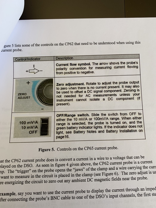
gure 5 lists some of the controls on the CP62 that need to be understood when using this current probe. Control/Indicator Current flow symbol. The arrow shows the probe's polarity convention for measuring current flowing from positive to negative. Zero adjustment. Rotate to adjust the probe output to zero when there is no current present. It may also be used to offset a DC signal component. Zeroing is not needed for AC measurements unless your instrument cannot isolate a DC component (if present) ZERO ADJUST 100 mVIA 10 mVIA OFF OFF/Range switch. Slide the switch from OFF to either the 10 mVIA or 100mVIA range. When either range is selected, the probe is turned on, and the green battery indicator lights. If the indicator does not light, see Battery Notes and Battery Installation on page16. Figure 5. Controls on the CP65 current probe. at the CP62 current probe does is convert a current in a wire to a voltage that can be layed on the DSO. As seen in figure 4 given above, the CP62 current probe is a current np. The "trigger" on the probe opens the "jaws" of the clamp and a wire carrying the curr want to measure in the circuit is placed in the clamp (see Figure 6). The zero adjust is us re energizing the circuit to zero out any ambient DC magnetic fields near the probe. example, say you want to use the current probe to display the current through an imped fter connecting the probe's BNC cable to one of the DSO's input channels, the first st
i(t) Figure 6. Measuring current i(t) through impedance Z. There is an arrow (the "Current Flow Symbol") stamped on the side of the probe as indicated here. If the arrow "Current Flow Symbol") stamped on the side of the clamp is reversed, your measured i(t) will be 180° out of phase with what you expect it to be. You need to be aware of the arrow for the same reason you need to be aware of the t probe leads when using the DMM to measure a current. Next, set the Range Switch on the probe to 10 mV 100A This does two things: it powers up the current probe and sets the probe's sensitivity or conversion factor. By the way, a 9V wall transformer (AC to DC converter) is the power supply for the current probes used in lab. For example, say you have clamped the current probe as described above onto a wire and you have set the Range Switch to 10 In Channel 1 of the DSO you have the FG supply voltage to give you a time reference and in Channel 2 you have the current probe output. Your DSO display gives you the traces vi and v2 shown in Figure 7
Homework Answers

 1)DSO has a Cathode ray
oscilloscope which is essentially a voltmeter.For other
functionality ,like current,phase etc. we need transducer to
convert them into voltages.So DSO originnaly is a voltmeter and is
operated in voltages.
1)DSO has a Cathode ray
oscilloscope which is essentially a voltmeter.For other
functionality ,like current,phase etc. we need transducer to
convert them into voltages.So DSO originnaly is a voltmeter and is
operated in voltages.
Add Answer to:
1. Why can the DSO only measure node voltages when the Function Generator is the power supply in ...
The two circuits you will model in Multisim and then build on the protoboard are the...
 The two circuits you will model in Multisim and then build on the protoboard are the RC and RL circuits shown in Figures 5 and 6 below. In all cases, make the voltage supply the time reference voltage as indicated in Equation 18 (18) Keep in mind that Vso and o will not be the same for both circuits. The RC Circuit The RC Circuit is shown in Figure 5. The capacitor will have a sinusoidal voltage drop given by...
INSTRUCTIONS: Read the questions carefully and answer the following items accordingly. Show your solution properly. Q7...
 INSTRUCTIONS: Read the questions carefully and answer the following items accordingly. Show your solution properly. Q7 A technician made an experiment of an AC circuit in an electrical lab. The source voltage is AC with a frequency of 60Hz. He collected the data in the form of a phasor diagram as shown Figure 3. This phasor diagram is an impedance phasor. The values in the diagram are reactances, a resistance and current. The current in this case is the reference...
Answer Q2 Q1. Use MATLAB to calculate sum of the AC voltages. Plot all three voltages...
 Answer Q2
Q1. Use MATLAB to calculate sum of the AC voltages. Plot all three voltages in the same figure using the inbuilt function subplot(). The frequency of the signal is 10 Hz. Vary the time, t, so that you can view few cycles of the AC voltage. vi(t) = 10 V sin(wt +T/2) vz(t) =15 V sin(wt+1/3) vs(t) = (t) + v2(t) Q2. Use voltage vi(t) from Q1 and impedance, Z = 50 L 30°, and find phasor current...
Answer Q2
Q1. Use MATLAB to calculate sum of the AC voltages. Plot all three voltages in the same figure using the inbuilt function subplot(). The frequency of the signal is 10 Hz. Vary the time, t, so that you can view few cycles of the AC voltage. vi(t) = 10 V sin(wt +T/2) vz(t) =15 V sin(wt+1/3) vs(t) = (t) + v2(t) Q2. Use voltage vi(t) from Q1 and impedance, Z = 50 L 30°, and find phasor current...
1. RL Circuits For the circuit in Figure 1, find the inductor voltage vit) if a)...
 1. RL Circuits For the circuit in Figure 1, find the inductor voltage vit) if a) v(t) is the step function: 0 Vfor t<0 and 10 V for t>0. What is the time constant in this case? b) vs(t) 15 cos(100 t). You may use either the direct time-domain method, or use (complex) phasor method. 52 102 5mH L(t) Figure 1 2. Impedance You are given six black boxes, labelled "1" to ", each with two terminals. You are told...
B oth 100 Day PH262 Page 1 of 5 Lab #13 AC Circuits, Part 1 RC...
 B oth 100 Day PH262 Page 1 of 5 Lab #13 AC Circuits, Part 1 RC & RL, Phase Measurements THEORY The rotating phase representation for series AC circuits should be familiar from textbook and lecture notes A brief outline of the essential points is provided here. If a series RLC circuit is connected across a source of om which is a sinusoidal function of time, then und all its derivatives will also be inside. Sonce all demits in a...
1. Is the power supply for a transformer AC or DC? Explain in detail why only...
1. Is the power supply for a transformer AC or DC? Explain in detail why only this type of power supply will work. 2. Some configurations with the iron core have low efficiency while others have high efficiency. What is the iron core doing to cause this? Be specific. (Hint: think about how a transformer works.) 3. For an ideal transformer the energy must be conserved, so the average power (P=IV) in the two circuits must be equal. Therefore, if...
1. Is the current through the power supply and each bulb (in Table 2) increasing or...
 1. Is the current through the power supply and each bulb (in
Table 2) increasing or decreasing with increasing the number of
bulbs in Fig. 5 (a) to Fig. 5 (d)? Why
2. Is there any correlation between the current through each
bulb and observed bulbs' brightness? Why?
3. Are the lights at your home connected in parallel? Why?
4. The maximum output current from the DC power supply #1 is 2
A. What is the maximum number of light...
1. Is the current through the power supply and each bulb (in
Table 2) increasing or decreasing with increasing the number of
bulbs in Fig. 5 (a) to Fig. 5 (d)? Why
2. Is there any correlation between the current through each
bulb and observed bulbs' brightness? Why?
3. Are the lights at your home connected in parallel? Why?
4. The maximum output current from the DC power supply #1 is 2
A. What is the maximum number of light...
Learning Goal: To understand the use of phasor diagrams in calculating the impedance and resonance conditions in a seri...
 Learning Goal: To understand the use of phasor diagrams in calculating the impedance and resonance conditions in a series L-R-C circuit. At resonance, XL = Xc. The voltage across the capacitor exactly cancels that across the i have the same amplitude. Thus, the inductor and capacitor effectively cancel out in the formu not come as a surprise that the resonant frequency equals the natural frequency of the oscilla In this problem, you will consider a series L-R-C circuit, containing a...
Can you please sow the work for the highlighted portion of the question. I have no...
 Can you please sow the work for the highlighted portion of the
question. I have no idea how that is found. Please show all steps.
Thanks
4, A 50 Ω lossless transmission line of 2 ¼ λ long is connected to an AC source, having a phasor voltage V,- 15 V and a terminal impedance of 50 Ω, and a load Z-50 +j 100 Ω. 1) Draw a schematic of this transmission line circuit; 2) Find the power delivered to...
Can you please sow the work for the highlighted portion of the
question. I have no idea how that is found. Please show all steps.
Thanks
4, A 50 Ω lossless transmission line of 2 ¼ λ long is connected to an AC source, having a phasor voltage V,- 15 V and a terminal impedance of 50 Ω, and a load Z-50 +j 100 Ω. 1) Draw a schematic of this transmission line circuit; 2) Find the power delivered to...
PLEASE SOLVE QUESTION NUMBER 2 ONLY, MAKE SURE ALL PARTS IN QUESTION 2 ARE SOLVED. THANK...
 PLEASE SOLVE QUESTION NUMBER 2 ONLY, MAKE SURE ALL PARTS IN
QUESTION 2 ARE SOLVED. THANK YOU
poirmts) l'igure output y ws an RG circuit with inpu Function Generator Model Capacitor Model i,(t) Figure 2: RC cireuit (a) (1 point) Sketch the circuit in the phasor domain by replacing the capacitor with its impedance represen- tation (b) (3 points) Using circuit analysis techniques, show that the frequency response function is F(u) UT 1 Specify the DC gain, K, and time...
PLEASE SOLVE QUESTION NUMBER 2 ONLY, MAKE SURE ALL PARTS IN
QUESTION 2 ARE SOLVED. THANK YOU
poirmts) l'igure output y ws an RG circuit with inpu Function Generator Model Capacitor Model i,(t) Figure 2: RC cireuit (a) (1 point) Sketch the circuit in the phasor domain by replacing the capacitor with its impedance represen- tation (b) (3 points) Using circuit analysis techniques, show that the frequency response function is F(u) UT 1 Specify the DC gain, K, and time...
 The two circuits you will model in Multisim and then build on the protoboard are the RC and RL circuits shown in Figures 5 and 6 below. In all cases, make the voltage supply the time reference voltage as indicated in Equation 18 (18) Keep in mind that Vso and o will not be the same for both circuits. The RC Circuit The RC Circuit is shown in Figure 5. The capacitor will have a sinusoidal voltage drop given by...
 INSTRUCTIONS: Read the questions carefully and answer the following items accordingly. Show your solution properly. Q7 A technician made an experiment of an AC circuit in an electrical lab. The source voltage is AC with a frequency of 60Hz. He collected the data in the form of a phasor diagram as shown Figure 3. This phasor diagram is an impedance phasor. The values in the diagram are reactances, a resistance and current. The current in this case is the reference...
 Answer Q2
Q1. Use MATLAB to calculate sum of the AC voltages. Plot all three voltages in the same figure using the inbuilt function subplot(). The frequency of the signal is 10 Hz. Vary the time, t, so that you can view few cycles of the AC voltage. vi(t) = 10 V sin(wt +T/2) vz(t) =15 V sin(wt+1/3) vs(t) = (t) + v2(t) Q2. Use voltage vi(t) from Q1 and impedance, Z = 50 L 30°, and find phasor current...
Answer Q2
Q1. Use MATLAB to calculate sum of the AC voltages. Plot all three voltages in the same figure using the inbuilt function subplot(). The frequency of the signal is 10 Hz. Vary the time, t, so that you can view few cycles of the AC voltage. vi(t) = 10 V sin(wt +T/2) vz(t) =15 V sin(wt+1/3) vs(t) = (t) + v2(t) Q2. Use voltage vi(t) from Q1 and impedance, Z = 50 L 30°, and find phasor current...
 1. RL Circuits For the circuit in Figure 1, find the inductor voltage vit) if a) v(t) is the step function: 0 Vfor t<0 and 10 V for t>0. What is the time constant in this case? b) vs(t) 15 cos(100 t). You may use either the direct time-domain method, or use (complex) phasor method. 52 102 5mH L(t) Figure 1 2. Impedance You are given six black boxes, labelled "1" to ", each with two terminals. You are told...
 B oth 100 Day PH262 Page 1 of 5 Lab #13 AC Circuits, Part 1 RC & RL, Phase Measurements THEORY The rotating phase representation for series AC circuits should be familiar from textbook and lecture notes A brief outline of the essential points is provided here. If a series RLC circuit is connected across a source of om which is a sinusoidal function of time, then und all its derivatives will also be inside. Sonce all demits in a...
 1. Is the current through the power supply and each bulb (in
Table 2) increasing or decreasing with increasing the number of
bulbs in Fig. 5 (a) to Fig. 5 (d)? Why
2. Is there any correlation between the current through each
bulb and observed bulbs' brightness? Why?
3. Are the lights at your home connected in parallel? Why?
4. The maximum output current from the DC power supply #1 is 2
A. What is the maximum number of light...
1. Is the current through the power supply and each bulb (in
Table 2) increasing or decreasing with increasing the number of
bulbs in Fig. 5 (a) to Fig. 5 (d)? Why
2. Is there any correlation between the current through each
bulb and observed bulbs' brightness? Why?
3. Are the lights at your home connected in parallel? Why?
4. The maximum output current from the DC power supply #1 is 2
A. What is the maximum number of light...
 Learning Goal: To understand the use of phasor diagrams in calculating the impedance and resonance conditions in a series L-R-C circuit. At resonance, XL = Xc. The voltage across the capacitor exactly cancels that across the i have the same amplitude. Thus, the inductor and capacitor effectively cancel out in the formu not come as a surprise that the resonant frequency equals the natural frequency of the oscilla In this problem, you will consider a series L-R-C circuit, containing a...
 Can you please sow the work for the highlighted portion of the
question. I have no idea how that is found. Please show all steps.
Thanks
4, A 50 Ω lossless transmission line of 2 ¼ λ long is connected to an AC source, having a phasor voltage V,- 15 V and a terminal impedance of 50 Ω, and a load Z-50 +j 100 Ω. 1) Draw a schematic of this transmission line circuit; 2) Find the power delivered to...
Can you please sow the work for the highlighted portion of the
question. I have no idea how that is found. Please show all steps.
Thanks
4, A 50 Ω lossless transmission line of 2 ¼ λ long is connected to an AC source, having a phasor voltage V,- 15 V and a terminal impedance of 50 Ω, and a load Z-50 +j 100 Ω. 1) Draw a schematic of this transmission line circuit; 2) Find the power delivered to...
 PLEASE SOLVE QUESTION NUMBER 2 ONLY, MAKE SURE ALL PARTS IN
QUESTION 2 ARE SOLVED. THANK YOU
poirmts) l'igure output y ws an RG circuit with inpu Function Generator Model Capacitor Model i,(t) Figure 2: RC cireuit (a) (1 point) Sketch the circuit in the phasor domain by replacing the capacitor with its impedance represen- tation (b) (3 points) Using circuit analysis techniques, show that the frequency response function is F(u) UT 1 Specify the DC gain, K, and time...
PLEASE SOLVE QUESTION NUMBER 2 ONLY, MAKE SURE ALL PARTS IN
QUESTION 2 ARE SOLVED. THANK YOU
poirmts) l'igure output y ws an RG circuit with inpu Function Generator Model Capacitor Model i,(t) Figure 2: RC cireuit (a) (1 point) Sketch the circuit in the phasor domain by replacing the capacitor with its impedance represen- tation (b) (3 points) Using circuit analysis techniques, show that the frequency response function is F(u) UT 1 Specify the DC gain, K, and time...
Most questions answered within 3 hours.
-
Where is the error in this code sequence?
String s1 = "Hello";
String s2 = "ello";...
asked 11 months ago -
Financial data for Joel de Paris, Inc., for last year
follow:
Joel de Paris, Inc.
Balance...
asked 11 months ago -
Consider this reaction:
Al2(SO4)3 (aq)+ BaCl3
(aq) Al2Cl6 (aq)- +
3BaSO4(s) . What is the...
asked 11 months ago -
Suppose that Savneet is considering increasing her
recent random sample from 20 car rentals to 40...
asked 11 months ago -
Trucks arrive at an unloading terminal at an average rate of 120
per hour.
Trucks arrive...
asked 11 months ago -
Why are methanol and ethanol completely soluble in water while
octanol is not very little soluble....
asked 11 months ago -
A facilities manager at a university reads in a research report
that the mean amount of...
asked 11 months ago -
When the CuSO4 is rehydrated by adding water to the anhydrous
compound, is this an endothermic...
asked 11 months ago -
A ray of sunlight is passing from diamond into crown glass; the
angle of incidence is...
asked 11 months ago -
A block of mass 0.249 kg is placed on top of a light, vertical
spring of...
asked 11 months ago -
how do the kidneys compensate in the presences of acidosis
a) trigger hyperventilate
b) reserve acid...
asked 11 months ago -
Question 501 pts
The rental rate of capital to the firm increases. Which of the
following...
asked 11 months ago