A low pass filter is made using a 50 pF capacitor and a 6 kΩ resistor...
A low pass filter is made using a 50 pF capacitor and a 6 kΩ resistor
- Draw the circuit
- What is the critical frequency of the filter in Hz?
- What is the attenuation of a 500 Hz signal?
- What is the attenuation of a 50 kHz signal?
- What is the 50 kHz attenuation in dB?
Homework Answers


The frequency at which the output voltage is 0.707 times the Input voltage ,is called the cut of frequency.
From the circuit ,By voltage division Rule:

if we put


so  so putting all the values in Equation(i)

Attenuation is defined as the loss of input signal in the transmission
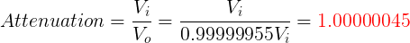

So using equation (i)
 So
So

 at f=50kHz
 Note:
the base of the log is 10.
Note:
the base of the log is 10.
Add Answer to:
A low pass filter is made using a 50 pF
capacitor and a 6 kΩ resistor...
2. A high pass filter is built using a 5k resistor and 200 pF capacitor. a....
 2. A high pass filter is built using a 5k resistor and 200 pF capacitor. a. Draw the circuit b. Calculate the time constant for the circuit c. What is the critical frequency (in rad/s) for the circuit? d. What is the critical frequency (in Hz) for the circuit? e. What is the attenuation for a 30 kHz signal? f. What is the attenuation for a 300 kHz signal? g. What is the 30 kHz attenuation in dB?
Using the windowing functions discussed in class, design a low-pass FIR filter with a cutoff freq...
 Using the windowing functions discussed in class, design a
low-pass FIR filter with a cutoff frequency of 2 kHz, a minimum
stop band attenuation of 40 dB, and a transition width of 200Hz.
The sampling frequency is 10kHz.
1. Using the windowing functions discussed in class, design a low-pass FIR filter with a cutoff frequency of 2 kHz, a minimum stop band attenuation of 40 dB, and a transition width of 200 Hz. The sampling frequency is 10 kHz 2....
Using the windowing functions discussed in class, design a
low-pass FIR filter with a cutoff frequency of 2 kHz, a minimum
stop band attenuation of 40 dB, and a transition width of 200Hz.
The sampling frequency is 10kHz.
1. Using the windowing functions discussed in class, design a low-pass FIR filter with a cutoff frequency of 2 kHz, a minimum stop band attenuation of 40 dB, and a transition width of 200 Hz. The sampling frequency is 10 kHz 2....
A) Design a low-pass filter using the given circuitry with a cut-off value of 1 kHz and plot the ...
 a) Design a low-pass filter using the given circuitry with a cut-off value of 1 kHz and plot the frequency response curve on the given axes 1.0 0.7 0.5 in out 0.0 101 102 103 104 10s Hz b) Design a band-pass filter using the given circuitry with a bandwidth of 500 Hz and a lower cut-off value of 100 Hz, and draw the frequency response curve. Keep all resistors at the same value (i.e. Ri-R-R3-R4). 1.0 0.7 0.5 0.0...
a) Insert a resistor R3 in series with the feedback capacitor C in the low pass...
 a) Insert a resistor R3 in series with the feedback capacitor C in the low pass filter of class. Draw the modified circuit. b) Derive the resulting transfer function. Simplify to the point that the pole and zero coefficients are apparent. c) Plot the transfer function with a DC gain of 0 dB. What is the value of the magnitude (in dB) at the frequency of the pole? At the frequency of the zero? d) If the pole frequency is...
Problem 3) (15 points) An RC filter is designed with a cutoff frequency of 100 Hz. If a low-pass first order filter is used, determine the attenuation (Attenuation %, and Attenuation(dB)) of the f...
 Problem 3) (15 points) An RC filter is designed with a cutoff frequency of 100 Hz. If a low-pass first order filter is used, determine the attenuation (Attenuation %, and Attenuation(dB)) of the filtered analog signal at 50, 75 and 200 Hz. (use k -1) o Determine the order of the filter if magnitude ratio of <0.01 is needed at 200 Hz.
Problem 3) (15 points) An RC filter is designed with a cutoff frequency of 100 Hz. If a...
Problem 3) (15 points) An RC filter is designed with a cutoff frequency of 100 Hz. If a low-pass first order filter is used, determine the attenuation (Attenuation %, and Attenuation(dB)) of the filtered analog signal at 50, 75 and 200 Hz. (use k -1) o Determine the order of the filter if magnitude ratio of <0.01 is needed at 200 Hz.
Problem 3) (15 points) An RC filter is designed with a cutoff frequency of 100 Hz. If a...
10 Design a low pass filter using a resistor R and a capacitor C of 0.2uF....
 10 Design a low pass filter using a resistor R and a capacitor C of 0.2uF. Sketch the circuit diagram, mark thoe output voltage Vo, calculate the resistance value for R if 3dB frequency is 2500 Hz, and write out the voltage gain vs ω (for both magnitude and phase). Repeat the design if R is given as 30 Ohm and C is unknown.
build a high pass filter using a capacitor and a resistor that eliminate 80% of a...
 build a high pass filter using a capacitor and a resistor that
eliminate 80% of a 60Hz portion of a signal. (a) Draw the circuit.
(b) Derive an equation for the ratio of the output voltage to the
input voltage. (c) find the capacitor needed if a R= 100 Ohm
resistor is used. (d) what percentage of the 10kHz signal is passed
by the high pass filter for the no load circuit?. (e) What is the
ratio of output signal...
build a high pass filter using a capacitor and a resistor that
eliminate 80% of a 60Hz portion of a signal. (a) Draw the circuit.
(b) Derive an equation for the ratio of the output voltage to the
input voltage. (c) find the capacitor needed if a R= 100 Ohm
resistor is used. (d) what percentage of the 10kHz signal is passed
by the high pass filter for the no load circuit?. (e) What is the
ratio of output signal...
For the low-pass filter circuit shown in Fig 2 3k Ω 200mil in out Fig 2 3.a. Use a 2.2nF capacitor to design a high-pas...
 For the low-pass filter circuit shown in Fig 2 3k Ω 200mil in out Fig 2 3.a. Use a 2.2nF capacitor to design a high-pass filter to have a cutoff frequency of Skn Draw a schematic of your design. Show all component values and voltages c. Sketch the frequency response of the voltage gain and phase shift Magnitude dB Frequency Hz Phase Frequency Hz
For the low-pass filter circuit shown in Fig 2 3k Ω 200mil in out Fig 2...
For the low-pass filter circuit shown in Fig 2 3k Ω 200mil in out Fig 2 3.a. Use a 2.2nF capacitor to design a high-pass filter to have a cutoff frequency of Skn Draw a schematic of your design. Show all component values and voltages c. Sketch the frequency response of the voltage gain and phase shift Magnitude dB Frequency Hz Phase Frequency Hz
For the low-pass filter circuit shown in Fig 2 3k Ω 200mil in out Fig 2...
Problem 1 (25 Pts) Design a low pass multistage Butterworth filter that simultaneously meets the following...
 Problem 1 (25 Pts) Design a low pass multistage Butterworth filter that simultaneously meets the following design requirements: 1. Minimum attenuation of 24 dB at 1000 Hz and 2. Minimum attenuation of 48 dB at frequency of 2000 Hz or higher. Consider equal source and load impedances at 50 S2. Part a) 15 pts Solve for both the order of the Butterworth filter and the cut-off frequency required to meet the above design criteria. Part b) 10 pts Find the...
Problem 1 (25 Pts) Design a low pass multistage Butterworth filter that simultaneously meets the following...
 Problem 1 (25 Pts) Design a low pass multistage Butterworth filter that simultaneously meets the following design requirements: 1. Minimum attenuation of 24 dB at 1000 Hz and 2. Minimum attenuation of 48 dB at frequency of 2000 Hz or higher. Consider equal source and load impedances at 50 2. Part a) 15 pts Solve for both the order of the Butterworth filter and the cut-off frequency required to meet the above design criteria Part b) 10 pts Find the...
 2. A high pass filter is built using a 5k resistor and 200 pF capacitor. a. Draw the circuit b. Calculate the time constant for the circuit c. What is the critical frequency (in rad/s) for the circuit? d. What is the critical frequency (in Hz) for the circuit? e. What is the attenuation for a 30 kHz signal? f. What is the attenuation for a 300 kHz signal? g. What is the 30 kHz attenuation in dB?
 Using the windowing functions discussed in class, design a
low-pass FIR filter with a cutoff frequency of 2 kHz, a minimum
stop band attenuation of 40 dB, and a transition width of 200Hz.
The sampling frequency is 10kHz.
1. Using the windowing functions discussed in class, design a low-pass FIR filter with a cutoff frequency of 2 kHz, a minimum stop band attenuation of 40 dB, and a transition width of 200 Hz. The sampling frequency is 10 kHz 2....
Using the windowing functions discussed in class, design a
low-pass FIR filter with a cutoff frequency of 2 kHz, a minimum
stop band attenuation of 40 dB, and a transition width of 200Hz.
The sampling frequency is 10kHz.
1. Using the windowing functions discussed in class, design a low-pass FIR filter with a cutoff frequency of 2 kHz, a minimum stop band attenuation of 40 dB, and a transition width of 200 Hz. The sampling frequency is 10 kHz 2....
 a) Design a low-pass filter using the given circuitry with a cut-off value of 1 kHz and plot the frequency response curve on the given axes 1.0 0.7 0.5 in out 0.0 101 102 103 104 10s Hz b) Design a band-pass filter using the given circuitry with a bandwidth of 500 Hz and a lower cut-off value of 100 Hz, and draw the frequency response curve. Keep all resistors at the same value (i.e. Ri-R-R3-R4). 1.0 0.7 0.5 0.0...
 a) Insert a resistor R3 in series with the feedback capacitor C in the low pass filter of class. Draw the modified circuit. b) Derive the resulting transfer function. Simplify to the point that the pole and zero coefficients are apparent. c) Plot the transfer function with a DC gain of 0 dB. What is the value of the magnitude (in dB) at the frequency of the pole? At the frequency of the zero? d) If the pole frequency is...
 Problem 3) (15 points) An RC filter is designed with a cutoff frequency of 100 Hz. If a low-pass first order filter is used, determine the attenuation (Attenuation %, and Attenuation(dB)) of the filtered analog signal at 50, 75 and 200 Hz. (use k -1) o Determine the order of the filter if magnitude ratio of <0.01 is needed at 200 Hz.
Problem 3) (15 points) An RC filter is designed with a cutoff frequency of 100 Hz. If a...
Problem 3) (15 points) An RC filter is designed with a cutoff frequency of 100 Hz. If a low-pass first order filter is used, determine the attenuation (Attenuation %, and Attenuation(dB)) of the filtered analog signal at 50, 75 and 200 Hz. (use k -1) o Determine the order of the filter if magnitude ratio of <0.01 is needed at 200 Hz.
Problem 3) (15 points) An RC filter is designed with a cutoff frequency of 100 Hz. If a...
 10 Design a low pass filter using a resistor R and a capacitor C of 0.2uF. Sketch the circuit diagram, mark thoe output voltage Vo, calculate the resistance value for R if 3dB frequency is 2500 Hz, and write out the voltage gain vs ω (for both magnitude and phase). Repeat the design if R is given as 30 Ohm and C is unknown.
 For the low-pass filter circuit shown in Fig 2 3k Ω 200mil in out Fig 2 3.a. Use a 2.2nF capacitor to design a high-pass filter to have a cutoff frequency of Skn Draw a schematic of your design. Show all component values and voltages c. Sketch the frequency response of the voltage gain and phase shift Magnitude dB Frequency Hz Phase Frequency Hz
For the low-pass filter circuit shown in Fig 2 3k Ω 200mil in out Fig 2...
For the low-pass filter circuit shown in Fig 2 3k Ω 200mil in out Fig 2 3.a. Use a 2.2nF capacitor to design a high-pass filter to have a cutoff frequency of Skn Draw a schematic of your design. Show all component values and voltages c. Sketch the frequency response of the voltage gain and phase shift Magnitude dB Frequency Hz Phase Frequency Hz
For the low-pass filter circuit shown in Fig 2 3k Ω 200mil in out Fig 2...
 Problem 1 (25 Pts) Design a low pass multistage Butterworth filter that simultaneously meets the following design requirements: 1. Minimum attenuation of 24 dB at 1000 Hz and 2. Minimum attenuation of 48 dB at frequency of 2000 Hz or higher. Consider equal source and load impedances at 50 S2. Part a) 15 pts Solve for both the order of the Butterworth filter and the cut-off frequency required to meet the above design criteria. Part b) 10 pts Find the...
 Problem 1 (25 Pts) Design a low pass multistage Butterworth filter that simultaneously meets the following design requirements: 1. Minimum attenuation of 24 dB at 1000 Hz and 2. Minimum attenuation of 48 dB at frequency of 2000 Hz or higher. Consider equal source and load impedances at 50 2. Part a) 15 pts Solve for both the order of the Butterworth filter and the cut-off frequency required to meet the above design criteria Part b) 10 pts Find the...
Most questions answered within 3 hours.
-
Where is the error in this code sequence?
String s1 = "Hello";
String s2 = "ello";...
asked 10 months ago -
Financial data for Joel de Paris, Inc., for last year
follow:
Joel de Paris, Inc.
Balance...
asked 10 months ago -
Consider this reaction:
Al2(SO4)3 (aq)+ BaCl3
(aq) Al2Cl6 (aq)- +
3BaSO4(s) . What is the...
asked 10 months ago -
Suppose that Savneet is considering increasing her
recent random sample from 20 car rentals to 40...
asked 10 months ago -
Trucks arrive at an unloading terminal at an average rate of 120
per hour.
Trucks arrive...
asked 10 months ago -
Why are methanol and ethanol completely soluble in water while
octanol is not very little soluble....
asked 10 months ago -
A facilities manager at a university reads in a research report
that the mean amount of...
asked 10 months ago -
When the CuSO4 is rehydrated by adding water to the anhydrous
compound, is this an endothermic...
asked 10 months ago -
A ray of sunlight is passing from diamond into crown glass; the
angle of incidence is...
asked 10 months ago -
A block of mass 0.249 kg is placed on top of a light, vertical
spring of...
asked 10 months ago -
how do the kidneys compensate in the presences of acidosis
a) trigger hyperventilate
b) reserve acid...
asked 10 months ago -
Question 501 pts
The rental rate of capital to the firm increases. Which of the
following...
asked 10 months ago