
Homework Answers
Add Answer to:
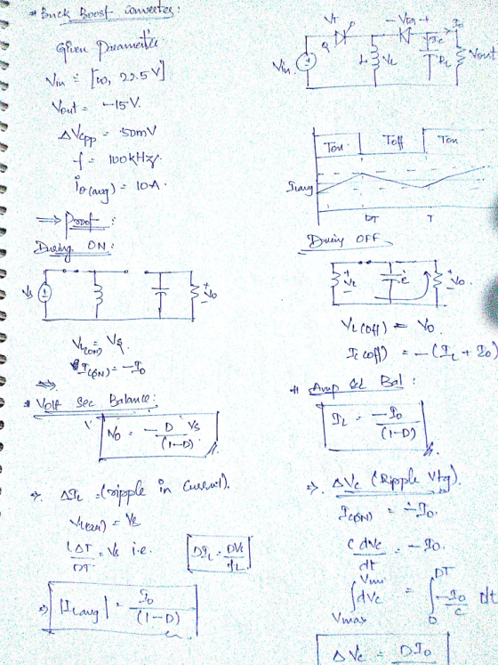
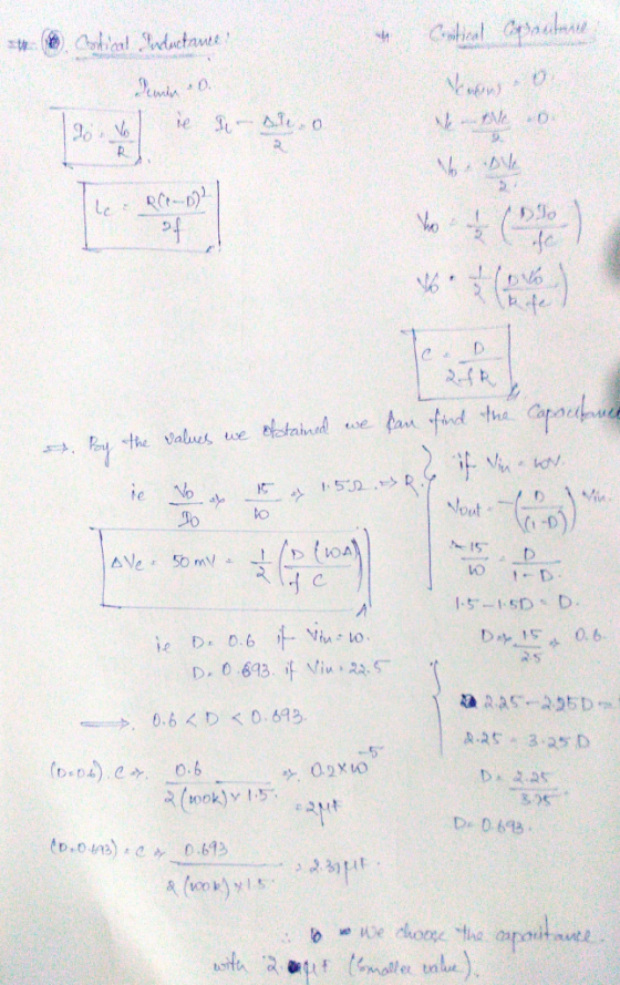
1) For a buck-boost converter, it is desired to have a peak-peak capacitor ripple (vc.pP) of 50 m...
1) (6 points) It is desired to design a 50 W buck-boost converter to regulate its...
 1) (6 points) It is desired to design a 50 W buck-boost converter to regulate its output voltage at 26V from a solar panel whose output voltage varies between 20 and 40 V. The desired switching frequency is 20 kHz. The ripple current in the inductor should remain within +/-0.1 A, and the output voltage ripple should not exceed +/- 2%. a. Determine the duty cycle range for operating this converter. b. Design this buck-boost converter by finding lower limits...
Please help in this question conserning the buck-boost converter 4. a. Draw a buck-boost converter to...
 Please help in this question conserning the buck-boost
converter
4. a. Draw a buck-boost converter to be implemented with an IGBT and diode b. Suggest suitable component values if such a converter is to serve resistive loads between 15 W and 30 W with a constant 8 V output, when the converter's input can vary between 5 V and 12 V. The output peak-to-peak voltage ripple should be less than 5% of the output voltage. The converter should operate in...
Please help in this question conserning the buck-boost
converter
4. a. Draw a buck-boost converter to be implemented with an IGBT and diode b. Suggest suitable component values if such a converter is to serve resistive loads between 15 W and 30 W with a constant 8 V output, when the converter's input can vary between 5 V and 12 V. The output peak-to-peak voltage ripple should be less than 5% of the output voltage. The converter should operate in...
A buck-boost converter has input voltage of 12V and operates with a duty cycle of 0.6...
A buck-boost converter has input voltage of 12V and operates with a duty cycle of 0.6 at a frequency of 50kHz and a load current of 5A average. Assuming sufficiently large L, and C = 500uF, calculate the peak-peak output voltage ripple and the rms current rating for the capacitor and inductor.
****Please ALL answers questions with complete steps.**** 1. Analysis and design of a buck-boost converter. A...
 ****Please ALL answers questions with complete
steps.****
1. Analysis and design of a buck-boost converter. A buck-boost converter is illustrated below. + licit) + reee c= R { v(t) A practical implementation using a MOSFET and diode is illustrated below. D + Voi(t) – H + iqi(t) IT int) lic(t) iz(t) + LE vi(t) c R v(t) For this problem, you must employ the methods of inductor volt-second balance, capacitor charge balance, and the small ripple approximation as discussed in...
****Please ALL answers questions with complete
steps.****
1. Analysis and design of a buck-boost converter. A buck-boost converter is illustrated below. + licit) + reee c= R { v(t) A practical implementation using a MOSFET and diode is illustrated below. D + Voi(t) – H + iqi(t) IT int) lic(t) iz(t) + LE vi(t) c R v(t) For this problem, you must employ the methods of inductor volt-second balance, capacitor charge balance, and the small ripple approximation as discussed in...
A Buck-boost converter has an output voltage 100 V, output power 60 W and input voltage...
A Buck-boost converter has an output voltage 100 V, output power 60 W and input voltage 12 V. Switching frequency is 15 kHz. Calculate duty ratios for the switch and the diode. Find values for the inductor L and capacitor C, when the allowed output voltage ripple is ±0.15 % and the inductor current ripple is ±1 % (of the average value). If the on-time of the switch has an inaccuracy of ±50 ns, what is the new output voltage...
In the following buck converter, let the switching frequency be 50 kHz. Determine if the converter...
In the following buck converter, let the switching frequency be 50 kHz. Determine if the converter is in CCM or DCM Compute the average inductor current, peak-peak current ripple Average transistor current, average diode current Peak current in the transistor Peak-peak ripple in the output voltage f.Power delivered by the input 12V source Vd=12 ,Vo=8V ,R=4ohm, L=20uH ,C=50uF
A buck converter is used to have low output voltage from the high input source to...
 A buck converter is used to have low output voltage from the high input source to low output voltage. The estimated power output is at 25 kW with the switching frequency of 25 kHz. Design the buck converter as by finding and following specifications consider the ripple of the output is set at 1% (i) Calculate the duty ratio of the buck converter (1 mark) (ii) Determine the minimum requirement for the inductor and the capacitor (5 marks) (iii) Determine...
Buck Converter Question Q3. A Buck converter is used to produce a regulated 10V, 5A DC...
 Buck Converter Question
Q3. A Buck converter is used to produce a regulated 10V, 5A DC power supply from a variable DC source with an nominal input voltage of Vin = 20V±5V. The Buck converter switches at 250kHz, and operates entirely in the continuous conduction mode. The output filter capacitance is C1.0uF 3.a. Draw the circuit topology for the Buck converter. Ensure that your circuit includes the input DC source, the output load resistance, the switching devices (i.e. MOSFET and...
Buck Converter Question
Q3. A Buck converter is used to produce a regulated 10V, 5A DC power supply from a variable DC source with an nominal input voltage of Vin = 20V±5V. The Buck converter switches at 250kHz, and operates entirely in the continuous conduction mode. The output filter capacitance is C1.0uF 3.a. Draw the circuit topology for the Buck converter. Ensure that your circuit includes the input DC source, the output load resistance, the switching devices (i.e. MOSFET and...
2.9 To reduce the switching harmonics present in the input current of a certain buck converter,...
 2.9 To reduce the switching harmonics present in the input current of a certain buck converter, an input filter consisting of inductor Li and capacitor Ci is added as shown in Fig. 2.32. Such filters are commonly used to meet regulations limiting conducted electromagnetic interference (EMI). For this problem, you may assume that all inductance and capacitance values are sufficiently large, such that all ripple magni- tudes are small CI Fig. 2.32 Addition of L-C input filter to buck converter,...
In the following buck converter, let the switching frequency be 50 kHz. Determine if the converter is in CCM or DCM ...
In the following buck converter, let the switching frequency be 50 kHz. Determine if the converter is in CCM or DCM Compute the average inductor current, peak-peak current ripple Average transistor current, average diode current Peak current in the transistor Peak-peak ripple in the output voltage f.Power delivered by the input 12V source Vd=12 ,Vo=8V ,R=4ohm, L=20uH ,C=50uF
 1) (6 points) It is desired to design a 50 W buck-boost converter to regulate its output voltage at 26V from a solar panel whose output voltage varies between 20 and 40 V. The desired switching frequency is 20 kHz. The ripple current in the inductor should remain within +/-0.1 A, and the output voltage ripple should not exceed +/- 2%. a. Determine the duty cycle range for operating this converter. b. Design this buck-boost converter by finding lower limits...
 Please help in this question conserning the buck-boost
converter
4. a. Draw a buck-boost converter to be implemented with an IGBT and diode b. Suggest suitable component values if such a converter is to serve resistive loads between 15 W and 30 W with a constant 8 V output, when the converter's input can vary between 5 V and 12 V. The output peak-to-peak voltage ripple should be less than 5% of the output voltage. The converter should operate in...
Please help in this question conserning the buck-boost
converter
4. a. Draw a buck-boost converter to be implemented with an IGBT and diode b. Suggest suitable component values if such a converter is to serve resistive loads between 15 W and 30 W with a constant 8 V output, when the converter's input can vary between 5 V and 12 V. The output peak-to-peak voltage ripple should be less than 5% of the output voltage. The converter should operate in...
 ****Please ALL answers questions with complete
steps.****
1. Analysis and design of a buck-boost converter. A buck-boost converter is illustrated below. + licit) + reee c= R { v(t) A practical implementation using a MOSFET and diode is illustrated below. D + Voi(t) – H + iqi(t) IT int) lic(t) iz(t) + LE vi(t) c R v(t) For this problem, you must employ the methods of inductor volt-second balance, capacitor charge balance, and the small ripple approximation as discussed in...
****Please ALL answers questions with complete
steps.****
1. Analysis and design of a buck-boost converter. A buck-boost converter is illustrated below. + licit) + reee c= R { v(t) A practical implementation using a MOSFET and diode is illustrated below. D + Voi(t) – H + iqi(t) IT int) lic(t) iz(t) + LE vi(t) c R v(t) For this problem, you must employ the methods of inductor volt-second balance, capacitor charge balance, and the small ripple approximation as discussed in...
 A buck converter is used to have low output voltage from the high input source to low output voltage. The estimated power output is at 25 kW with the switching frequency of 25 kHz. Design the buck converter as by finding and following specifications consider the ripple of the output is set at 1% (i) Calculate the duty ratio of the buck converter (1 mark) (ii) Determine the minimum requirement for the inductor and the capacitor (5 marks) (iii) Determine...
 Buck Converter Question
Q3. A Buck converter is used to produce a regulated 10V, 5A DC power supply from a variable DC source with an nominal input voltage of Vin = 20V±5V. The Buck converter switches at 250kHz, and operates entirely in the continuous conduction mode. The output filter capacitance is C1.0uF 3.a. Draw the circuit topology for the Buck converter. Ensure that your circuit includes the input DC source, the output load resistance, the switching devices (i.e. MOSFET and...
Buck Converter Question
Q3. A Buck converter is used to produce a regulated 10V, 5A DC power supply from a variable DC source with an nominal input voltage of Vin = 20V±5V. The Buck converter switches at 250kHz, and operates entirely in the continuous conduction mode. The output filter capacitance is C1.0uF 3.a. Draw the circuit topology for the Buck converter. Ensure that your circuit includes the input DC source, the output load resistance, the switching devices (i.e. MOSFET and...
 2.9 To reduce the switching harmonics present in the input current of a certain buck converter, an input filter consisting of inductor Li and capacitor Ci is added as shown in Fig. 2.32. Such filters are commonly used to meet regulations limiting conducted electromagnetic interference (EMI). For this problem, you may assume that all inductance and capacitance values are sufficiently large, such that all ripple magni- tudes are small CI Fig. 2.32 Addition of L-C input filter to buck converter,...
Most questions answered within 3 hours.
-
Where is the error in this code sequence?
String s1 = "Hello";
String s2 = "ello";...
asked 11 months ago -
Financial data for Joel de Paris, Inc., for last year
follow:
Joel de Paris, Inc.
Balance...
asked 11 months ago -
Consider this reaction:
Al2(SO4)3 (aq)+ BaCl3
(aq) Al2Cl6 (aq)- +
3BaSO4(s) . What is the...
asked 11 months ago -
Suppose that Savneet is considering increasing her
recent random sample from 20 car rentals to 40...
asked 11 months ago -
Trucks arrive at an unloading terminal at an average rate of 120
per hour.
Trucks arrive...
asked 11 months ago -
Why are methanol and ethanol completely soluble in water while
octanol is not very little soluble....
asked 11 months ago -
A facilities manager at a university reads in a research report
that the mean amount of...
asked 11 months ago -
When the CuSO4 is rehydrated by adding water to the anhydrous
compound, is this an endothermic...
asked 11 months ago -
A ray of sunlight is passing from diamond into crown glass; the
angle of incidence is...
asked 11 months ago -
A block of mass 0.249 kg is placed on top of a light, vertical
spring of...
asked 11 months ago -
how do the kidneys compensate in the presences of acidosis
a) trigger hyperventilate
b) reserve acid...
asked 11 months ago -
Question 501 pts
The rental rate of capital to the firm increases. Which of the
following...
asked 11 months ago