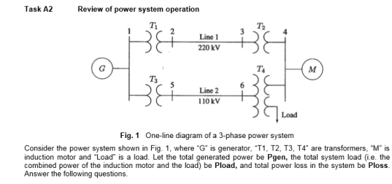

Please show steps for part a and b,
3) What would happen to the induction motor when Pgen is 1100kVA at 0.95 power factor leading, Pload is 1400kVA at 0.95 power factor lagging, Ploss is negligible; and machne is spining at its rated speed of 11 b) The induction machine is being started?
Homework Answers
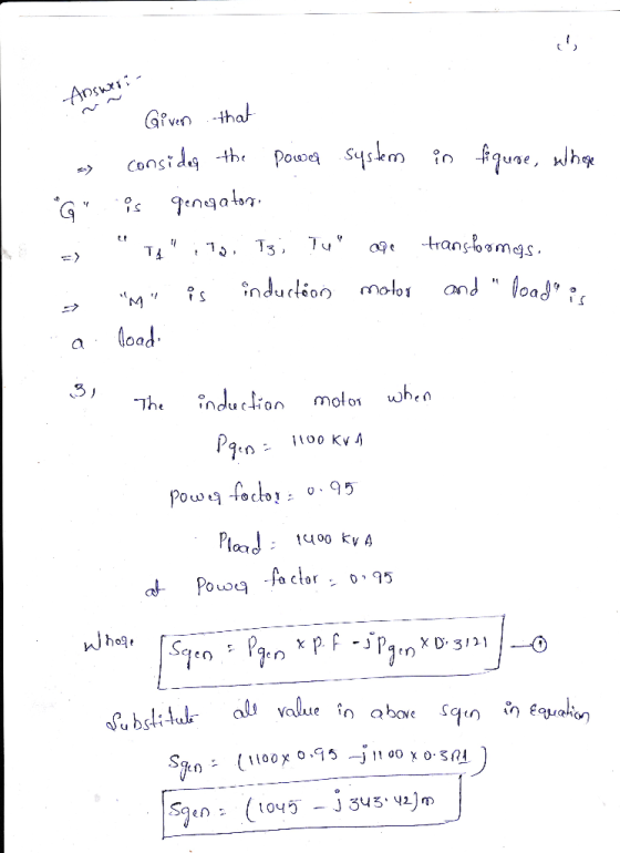
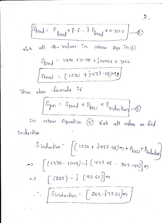

Add Answer to:
Task A2 Review of power system operation Ti Line 1 220 kv T3 Line 2 6 110 kV Load Fig. 1 One-line...
12. For a three-phase balanced system, a generator serves a remote load through two parallel tran...
 12. For a three-phase balanced system, a generator serves a remote load through two parallel transmission lines with 4 transformers. The system parameters are as follows: Generator: T1: (A-Y, with Y side voltage leading) T2: (A-Y, with Y side voltage leading) T3: (A-Y, with Y side voltage leading) T4: (A-Y, with Y side voltage leading) Line-1 Line-2 Load 100MVA, 21kV, x-0.15pu 120MVA, 20Д/165Y kV, x-O.12pu 80MVA, 20A/1 10Y kV, x-O.1pu 120MVA, 165A/33Y kV, x-0.12pu 80MVA, 11ОД/33Y kV, x-O.1pu 30+j100 O...
Problem #2: (40 points) The three-phase power and line- given below line ratings of the electric ...
 Problem #2: (40 points) The three-phase power and line- given below line ratings of the electric power system shown are G:60 MVA, 20 kV, X = 9% Tr 50 MVA. 20/200 kV.x 1096 T2: 50 MVA, 20020 kV, X 10% M: 43.2 MVA, 18 kV, X 8% Line: 200 kV, Z 120+j200 Ti Line 00-MVA 1. Draw an impedance diagram showing all impedances in per-unit on a1 2. The motor is drawing 40 MVA, 0.8 power factor lagging at a...
The three-phase power and line-line ratings of the electric power system shown in Figure 2 are...
 The three-phase power and line-line ratings of the electric power system shown in Figure 2 are given below. T1 T2 V. 1 2 vm 9 Line G M Figure 2 One-line diagram for problem 2 G: T1: 60 MVA 50 MVA 50 MVA T2: Line: M: 20 kV 20/200 kV 200/20 kV 200 kV 18 kV X=9% X=10% X=10% Z=120+j200 12 X=8% 43.2 MVA (a) Draw an impedance diagram showing all impedances in per unit on a 100-MVA base. Choose...
Four-bus power system shown in Fig. 1 are as follows: Generator G1: 200 MVA, 7.2 kv,...
 Four-bus power system shown in Fig. 1 are as follows: Generator G1: 200 MVA, 7.2 kv, X -0.15 p.u Generator G2: 250 MVA, 9.6 kV, X-0.12 p.u Generator G3: 500 MVA, 10 kV, X-0.25 p.u Transformer T1:200 MVA, 7.2 Δ /132 Y kV, X= 0.05 p.u Transformer T2: 250 MVA, 9.6 Δ /132 Y kV, X =0.15 p.u Transformer T3: 500 MVA, 10 Δ /132 Y kV, x-0.1 p.u Each 132-kV line:X,-10 Ω 1- A three-phase short circuit occurs at...
The three-phase power and line-line ratings of the electric power system shown in Figure 2 are...
 The three-phase power and line-line ratings of the electric power system shown in Figure 2 are given below T2 2 Line Vm G M 1 BA Figure 2 One-line diagram for problem 2 G: Ti: T2: Line: M: 60 MVA 50 MVA 50 MVA 20 kV 20/200 kV 200/20 kV 200 kV 18 kV X=9% X=10% X=10% Z=120+j2002 X=8% 43.2 MVA (a) Draw an impedance diagram showing all impedances in per unit on a 100-MVA base. Choose 20 kV as...
2 - The three-phase power and line-line ratings of the electric power system shown in Figure...
 2 - The three-phase power and line-line ratings of the electric power system shown in Figure 2 are given below. Ti T2 VA Line 2 G M Vm BE BE Figure 2 One-line diagram for problem 2 G: T: T2: Line: M: 60 MVA 50 MVA 50 MVA 20 kV 20/200 kV 200/20 kV 200 kV 18 kV X=9% X=10% X=10% Z=120+j2002 X=8% 43.2 MVA (a) Draw an impedance diagram showing all impedances in per unit on a 100-MVA base....
Please show me step by step how to get load impedance in per-unit. New load is 1.05+1.4j per unit...
 Please show me step by step how to get load impedance in
per-unit. New load is 1.05+1.4j per unit and new z load is 0.447
per unit
Consider the three-phase power system in the figure below. By selecting a common base of 100 MVA and 22 kV on the generator side, draw an impedance diagram showing all impedances, including the load impedance in per-unit. Lines 1 and 2 have series reactances of 48.4 and 65.43 2, respectively. At bus 4,...
Please show me step by step how to get load impedance in
per-unit. New load is 1.05+1.4j per unit and new z load is 0.447
per unit
Consider the three-phase power system in the figure below. By selecting a common base of 100 MVA and 22 kV on the generator side, draw an impedance diagram showing all impedances, including the load impedance in per-unit. Lines 1 and 2 have series reactances of 48.4 and 65.43 2, respectively. At bus 4,...
INTRODUCTION TO POWER SYSTEM
 1. The one-line diagram of a three-pha se power system is shown in Figure 3.29. Select a common base of 100 MVA and 15 kV on the motor side. Draw an impedance diagram with all impedances including the load impedance marked in per-unit. The manufacturer's data for each device is given as follow:The three-phase load at bus 4 absorbs 57 MVA, 0.6 power factor lagging at 10.45 kV. Line 1 and line 2 have reactances of 48.4 Ω and 65.43...
QUESTION 5 a) Define the Per Unit system and list three (3) main reasons of using Per Unit system...
 Per unit calculation
QUESTION 5 a) Define the Per Unit system and list three (3) main reasons of using Per Unit systemm. (5 marks) b) A three-bus power with two generator system is shown in figure Q2 (b). The 3-phase power and line-line voltage ratings are given below Ti T2 J40 2 Gi G2 j25 Ω 25 Ω Ty Figure Q2 (b) GI: 750 MVA, 18 kV, X 7% G2: 750 MVA, 18 kV, X-15% Motor: 1500 MVA, 20 kV,...
Per unit calculation
QUESTION 5 a) Define the Per Unit system and list three (3) main reasons of using Per Unit systemm. (5 marks) b) A three-bus power with two generator system is shown in figure Q2 (b). The 3-phase power and line-line voltage ratings are given below Ti T2 J40 2 Gi G2 j25 Ω 25 Ω Ty Figure Q2 (b) GI: 750 MVA, 18 kV, X 7% G2: 750 MVA, 18 kV, X-15% Motor: 1500 MVA, 20 kV,...
INTRODUCTION TO POWER SYSTEM
 1. The one-line diagram of a three-pha se power system is shown in Figure 3.29. Select a common base of 100 MVA and 15 kV on the motor side. Draw an impedance diagram with all impedances including the load impedance marked in per-unit. The manufacturer's data for each device is given as follow:The three-phase load at bus 4 absorbs 57 MVA, 0.6 power factor lagging at 10.45 kV. Line 1 and line 2 have reactances of 48.4 Ω and 65.43...
 12. For a three-phase balanced system, a generator serves a remote load through two parallel transmission lines with 4 transformers. The system parameters are as follows: Generator: T1: (A-Y, with Y side voltage leading) T2: (A-Y, with Y side voltage leading) T3: (A-Y, with Y side voltage leading) T4: (A-Y, with Y side voltage leading) Line-1 Line-2 Load 100MVA, 21kV, x-0.15pu 120MVA, 20Д/165Y kV, x-O.12pu 80MVA, 20A/1 10Y kV, x-O.1pu 120MVA, 165A/33Y kV, x-0.12pu 80MVA, 11ОД/33Y kV, x-O.1pu 30+j100 O...
 Problem #2: (40 points) The three-phase power and line- given below line ratings of the electric power system shown are G:60 MVA, 20 kV, X = 9% Tr 50 MVA. 20/200 kV.x 1096 T2: 50 MVA, 20020 kV, X 10% M: 43.2 MVA, 18 kV, X 8% Line: 200 kV, Z 120+j200 Ti Line 00-MVA 1. Draw an impedance diagram showing all impedances in per-unit on a1 2. The motor is drawing 40 MVA, 0.8 power factor lagging at a...
 The three-phase power and line-line ratings of the electric power system shown in Figure 2 are given below. T1 T2 V. 1 2 vm 9 Line G M Figure 2 One-line diagram for problem 2 G: T1: 60 MVA 50 MVA 50 MVA T2: Line: M: 20 kV 20/200 kV 200/20 kV 200 kV 18 kV X=9% X=10% X=10% Z=120+j200 12 X=8% 43.2 MVA (a) Draw an impedance diagram showing all impedances in per unit on a 100-MVA base. Choose...
 Four-bus power system shown in Fig. 1 are as follows: Generator G1: 200 MVA, 7.2 kv, X -0.15 p.u Generator G2: 250 MVA, 9.6 kV, X-0.12 p.u Generator G3: 500 MVA, 10 kV, X-0.25 p.u Transformer T1:200 MVA, 7.2 Δ /132 Y kV, X= 0.05 p.u Transformer T2: 250 MVA, 9.6 Δ /132 Y kV, X =0.15 p.u Transformer T3: 500 MVA, 10 Δ /132 Y kV, x-0.1 p.u Each 132-kV line:X,-10 Ω 1- A three-phase short circuit occurs at...
 The three-phase power and line-line ratings of the electric power system shown in Figure 2 are given below T2 2 Line Vm G M 1 BA Figure 2 One-line diagram for problem 2 G: Ti: T2: Line: M: 60 MVA 50 MVA 50 MVA 20 kV 20/200 kV 200/20 kV 200 kV 18 kV X=9% X=10% X=10% Z=120+j2002 X=8% 43.2 MVA (a) Draw an impedance diagram showing all impedances in per unit on a 100-MVA base. Choose 20 kV as...
 2 - The three-phase power and line-line ratings of the electric power system shown in Figure 2 are given below. Ti T2 VA Line 2 G M Vm BE BE Figure 2 One-line diagram for problem 2 G: T: T2: Line: M: 60 MVA 50 MVA 50 MVA 20 kV 20/200 kV 200/20 kV 200 kV 18 kV X=9% X=10% X=10% Z=120+j2002 X=8% 43.2 MVA (a) Draw an impedance diagram showing all impedances in per unit on a 100-MVA base....
 Please show me step by step how to get load impedance in
per-unit. New load is 1.05+1.4j per unit and new z load is 0.447
per unit
Consider the three-phase power system in the figure below. By selecting a common base of 100 MVA and 22 kV on the generator side, draw an impedance diagram showing all impedances, including the load impedance in per-unit. Lines 1 and 2 have series reactances of 48.4 and 65.43 2, respectively. At bus 4,...
Please show me step by step how to get load impedance in
per-unit. New load is 1.05+1.4j per unit and new z load is 0.447
per unit
Consider the three-phase power system in the figure below. By selecting a common base of 100 MVA and 22 kV on the generator side, draw an impedance diagram showing all impedances, including the load impedance in per-unit. Lines 1 and 2 have series reactances of 48.4 and 65.43 2, respectively. At bus 4,...
 Per unit calculation
QUESTION 5 a) Define the Per Unit system and list three (3) main reasons of using Per Unit systemm. (5 marks) b) A three-bus power with two generator system is shown in figure Q2 (b). The 3-phase power and line-line voltage ratings are given below Ti T2 J40 2 Gi G2 j25 Ω 25 Ω Ty Figure Q2 (b) GI: 750 MVA, 18 kV, X 7% G2: 750 MVA, 18 kV, X-15% Motor: 1500 MVA, 20 kV,...
Per unit calculation
QUESTION 5 a) Define the Per Unit system and list three (3) main reasons of using Per Unit systemm. (5 marks) b) A three-bus power with two generator system is shown in figure Q2 (b). The 3-phase power and line-line voltage ratings are given below Ti T2 J40 2 Gi G2 j25 Ω 25 Ω Ty Figure Q2 (b) GI: 750 MVA, 18 kV, X 7% G2: 750 MVA, 18 kV, X-15% Motor: 1500 MVA, 20 kV,...
Most questions answered within 3 hours.
-
Where is the error in this code sequence?
String s1 = "Hello";
String s2 = "ello";...
asked 11 months ago -
Financial data for Joel de Paris, Inc., for last year
follow:
Joel de Paris, Inc.
Balance...
asked 11 months ago -
Consider this reaction:
Al2(SO4)3 (aq)+ BaCl3
(aq) Al2Cl6 (aq)- +
3BaSO4(s) . What is the...
asked 11 months ago -
Suppose that Savneet is considering increasing her
recent random sample from 20 car rentals to 40...
asked 11 months ago -
Trucks arrive at an unloading terminal at an average rate of 120
per hour.
Trucks arrive...
asked 11 months ago -
Why are methanol and ethanol completely soluble in water while
octanol is not very little soluble....
asked 11 months ago -
A facilities manager at a university reads in a research report
that the mean amount of...
asked 11 months ago -
When the CuSO4 is rehydrated by adding water to the anhydrous
compound, is this an endothermic...
asked 11 months ago -
A ray of sunlight is passing from diamond into crown glass; the
angle of incidence is...
asked 11 months ago -
A block of mass 0.249 kg is placed on top of a light, vertical
spring of...
asked 11 months ago -
how do the kidneys compensate in the presences of acidosis
a) trigger hyperventilate
b) reserve acid...
asked 11 months ago -
Question 501 pts
The rental rate of capital to the firm increases. Which of the
following...
asked 11 months ago