Determine the Design Shear and Moment Strengths (φvVn and φbMn) for the following beams (length, ...
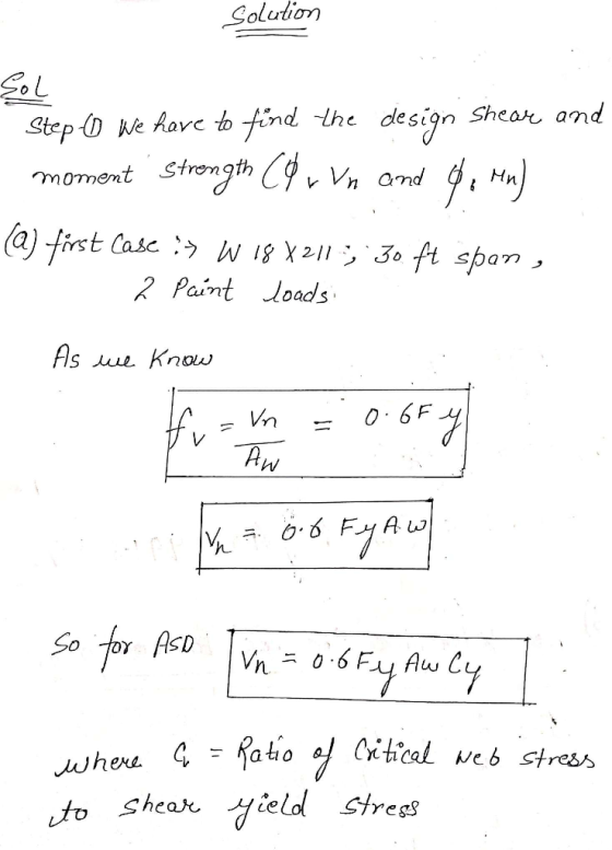
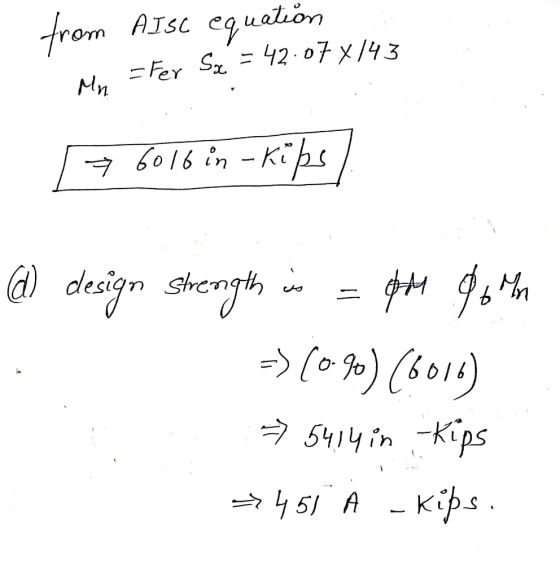
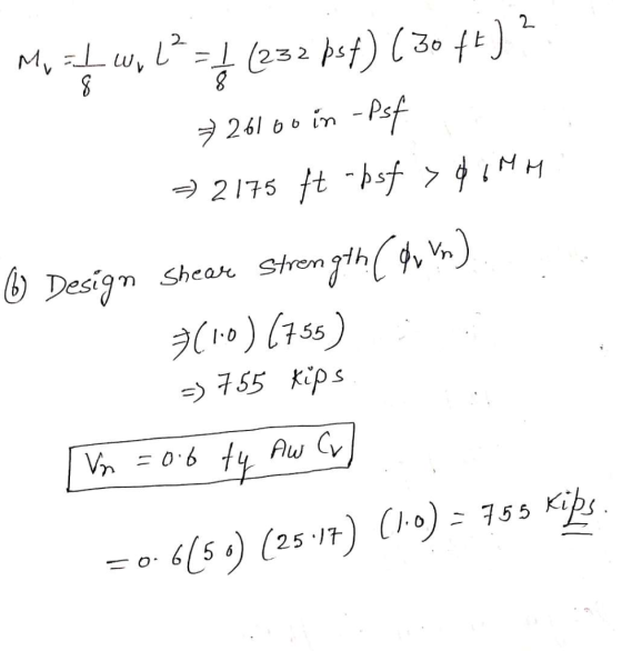
Determine the Design Shear and Moment Strengths (φvVn and φbMn) for the following beams (length, loading type and bracing points to determine Lb and Cb):
- W18x211; 30 ft span, 2 symmetric point loads which are braced
- M12.5x12.4; 20 ft span, uniform load, no bracing
- S15x50; 25 ft span, uniform load, single brace at midpoint
Using Table 3-10, design the least weight member for the following beam
- 30 ft span, uniform load, unbraced, beam spacing 25 ft, DL = 60psf LL = 100psf
Homework Answers
Add Answer to:
Determine the Design Shear and Moment Strengths (φvVn and φbMn) for the following beams (length, ...
Determine the Design Shear and Moment Strengths (φvVn and φbMn) for the following beams (length, loading...
Determine the Design Shear and Moment Strengths (φvVn and φbMn) for the following beams (length, loading type and bracing points to determine Lb and Cb): W18x211; 30 ft span, 2 symmetric point loads which are braced M12.5x12.4; 20 ft span, uniform load, no bracing S15x50; 25 ft span, uniform load, single brace at midpoint Using Table 3-10, design the least weight member for the following beam 30 ft span, uniform load, unbraced, beam spacing 25 ft, DL = 60psf LL...
. Design a beam for a 30-ft simple span to support the working uniform loads of...
 . Design a beam for a 30-ft simple span to support the working uniform loads of wo 1.25 k/ft (includes beam self-weight) and wi-1.75 k/ft. The maximum permissible total load deflection under working loads is 1/360 of the span. Use 50 ksi steel and consider moment, shear and deflection. The beam is to be braced laterally at its ends and the mid-span only. (25-POINTS)
Problem l The beam shown below is laterally braced at D,F and F. The uniform load shown does not include the weight of the beam. Determine whether a W24x 104 ASTM A992 is adequate for bending and sh...
 Problem l The beam shown below is laterally braced at D,F and F. The uniform load shown does not include the weight of the beam. Determine whether a W24x 104 ASTM A992 is adequate for bending and shear. P,-12k PL -36k 3k/ft 10 20 30 FIGURE P5.5-15 a) Determine the controlling load combination and calculate Pu (for the concentrated force) and wu (for wo plus beam's selfweight, which is a uniformly distributed load) b) Analyze the beam loaded with the...
A simply supported beam (B-2) supports a uniformly distributed load and is braced at five-foot in...
 A simply supported beam (B-2) supports a uniformly distributed
load and is braced at five-foot intervals in addition to a
composite slab that is secured to the compression flange of the
beam via shear studs. Assume that the beam is made of ASTM A992
grade with Fy = 50 ksi.
Select the lightest W shape to safely support the following
loads:
DL = 225 psf LL = 150 psf
Beams are spaced at 10' o.c.
8.25*: A simply supported beam...
A simply supported beam (B-2) supports a uniformly distributed
load and is braced at five-foot intervals in addition to a
composite slab that is secured to the compression flange of the
beam via shear studs. Assume that the beam is made of ASTM A992
grade with Fy = 50 ksi.
Select the lightest W shape to safely support the following
loads:
DL = 225 psf LL = 150 psf
Beams are spaced at 10' o.c.
8.25*: A simply supported beam...
1. The floor framing plan is shown below. Design the beams B1, B2, and Ba Check...
 1. The floor framing plan is shown below. Design the beams B1, B2, and Ba Check the beam weight for each beam. The bay does not repeat. Note The dead load does not include the weight of the beam Select the most economical section for each design to be fully laterally braced. Use A36 steel where Beam B1 frames into it only. Use A992 Grade 50 steel is considered fully braced by the slab it supports. Use A992 Grade 50...
For Problems 1 and 2, design rectangular sections for the beams. Loads and Density values are...
 For Problems 1 and 2, design rectangular sections for the beams.
Loads and Density values are shown. Beam weights are not included
in the loads shown. Show sketches of cross sections, including bar
sizes, arrangement, and spacing. Assume concrete weighs 150
lb/ft3, fy = 60,000 psi, and fc′ =4000 psi, unless given
otherwise.
2. Design a cantilever beam. The loading cases are shown in Figure 2: Wp = 3 k/ft, w, = 1 kft MITIMIZ 12f- Use p= 0.1852 Figure...
For Problems 1 and 2, design rectangular sections for the beams.
Loads and Density values are shown. Beam weights are not included
in the loads shown. Show sketches of cross sections, including bar
sizes, arrangement, and spacing. Assume concrete weighs 150
lb/ft3, fy = 60,000 psi, and fc′ =4000 psi, unless given
otherwise.
2. Design a cantilever beam. The loading cases are shown in Figure 2: Wp = 3 k/ft, w, = 1 kft MITIMIZ 12f- Use p= 0.1852 Figure...
Problem 1 (100 pts) Select the lightest W24 beam section with Fy = 50 ksi using...
 Problem 1 (100 pts) Select the lightest W24 beam section with Fy = 50 ksi using LRFD for the following span and loading. The unbraced length of the compression flange is 30 ft (Lb = 30'). Consider Cb > 1. The given dead load does not include beam weight. Verify that the selected beam has adequate shear strength. Maximum allowable deflection due to live load is L720. Maximum allowable deflection due to total load is L/360. WD = 1.2 k/ft...
Problem 1 Reinforced Concrete T-Flanged Sections (50 pts.) You are required to analyze and design...
 Problem 1 Reinforced Concrete T-Flanged Sections (50 pts.) You are required to analyze and design the propped cantilever t-section from HM 4 but for shear only. Draw shear V and moment M diagrams for uniformly distributed load throughout the 30ft span and equally concentrated loads at 10ft and 30ft. Recall that the connection at the left joint N1 is fixed. The connection at 20ft N3 is a roller. The right end node N2 is a free end. Use a concrete...
Problem 1 Reinforced Concrete T-Flanged Sections (50 pts.) You are required to analyze and design...
 Problem 1 Reinforced Concrete T-Flanged Sections (50 pts.) You are required to analyze and design the propped cantilever t-section from HM 4 but for shear only. Draw shear V and moment M diagrams for uniformly distributed load throughout the 30ft span and equally concentrated loads at 10ft and 30ft. Recall that the connection at the left joint N1 is fixed. The connection at 20ft N3 is a roller. The right end node N2 is a free end. Usea concrete compressive...
Find the design shear load for the following simply supported beam if the dead loads (include...
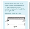 Find the design shear load for the following simply supported beam if the dead loads (include beam weights) is 1 k/ft and live load 2 k/ft., span length 35 ft. your answer should be in kips. span
 . Design a beam for a 30-ft simple span to support the working uniform loads of wo 1.25 k/ft (includes beam self-weight) and wi-1.75 k/ft. The maximum permissible total load deflection under working loads is 1/360 of the span. Use 50 ksi steel and consider moment, shear and deflection. The beam is to be braced laterally at its ends and the mid-span only. (25-POINTS)
 Problem l The beam shown below is laterally braced at D,F and F. The uniform load shown does not include the weight of the beam. Determine whether a W24x 104 ASTM A992 is adequate for bending and shear. P,-12k PL -36k 3k/ft 10 20 30 FIGURE P5.5-15 a) Determine the controlling load combination and calculate Pu (for the concentrated force) and wu (for wo plus beam's selfweight, which is a uniformly distributed load) b) Analyze the beam loaded with the...
 A simply supported beam (B-2) supports a uniformly distributed
load and is braced at five-foot intervals in addition to a
composite slab that is secured to the compression flange of the
beam via shear studs. Assume that the beam is made of ASTM A992
grade with Fy = 50 ksi.
Select the lightest W shape to safely support the following
loads:
DL = 225 psf LL = 150 psf
Beams are spaced at 10' o.c.
8.25*: A simply supported beam...
A simply supported beam (B-2) supports a uniformly distributed
load and is braced at five-foot intervals in addition to a
composite slab that is secured to the compression flange of the
beam via shear studs. Assume that the beam is made of ASTM A992
grade with Fy = 50 ksi.
Select the lightest W shape to safely support the following
loads:
DL = 225 psf LL = 150 psf
Beams are spaced at 10' o.c.
8.25*: A simply supported beam...
 1. The floor framing plan is shown below. Design the beams B1, B2, and Ba Check the beam weight for each beam. The bay does not repeat. Note The dead load does not include the weight of the beam Select the most economical section for each design to be fully laterally braced. Use A36 steel where Beam B1 frames into it only. Use A992 Grade 50 steel is considered fully braced by the slab it supports. Use A992 Grade 50...
 For Problems 1 and 2, design rectangular sections for the beams.
Loads and Density values are shown. Beam weights are not included
in the loads shown. Show sketches of cross sections, including bar
sizes, arrangement, and spacing. Assume concrete weighs 150
lb/ft3, fy = 60,000 psi, and fc′ =4000 psi, unless given
otherwise.
2. Design a cantilever beam. The loading cases are shown in Figure 2: Wp = 3 k/ft, w, = 1 kft MITIMIZ 12f- Use p= 0.1852 Figure...
For Problems 1 and 2, design rectangular sections for the beams.
Loads and Density values are shown. Beam weights are not included
in the loads shown. Show sketches of cross sections, including bar
sizes, arrangement, and spacing. Assume concrete weighs 150
lb/ft3, fy = 60,000 psi, and fc′ =4000 psi, unless given
otherwise.
2. Design a cantilever beam. The loading cases are shown in Figure 2: Wp = 3 k/ft, w, = 1 kft MITIMIZ 12f- Use p= 0.1852 Figure...
 Problem 1 (100 pts) Select the lightest W24 beam section with Fy = 50 ksi using LRFD for the following span and loading. The unbraced length of the compression flange is 30 ft (Lb = 30'). Consider Cb > 1. The given dead load does not include beam weight. Verify that the selected beam has adequate shear strength. Maximum allowable deflection due to live load is L720. Maximum allowable deflection due to total load is L/360. WD = 1.2 k/ft...
 Problem 1 Reinforced Concrete T-Flanged Sections (50 pts.) You are required to analyze and design the propped cantilever t-section from HM 4 but for shear only. Draw shear V and moment M diagrams for uniformly distributed load throughout the 30ft span and equally concentrated loads at 10ft and 30ft. Recall that the connection at the left joint N1 is fixed. The connection at 20ft N3 is a roller. The right end node N2 is a free end. Use a concrete...
 Problem 1 Reinforced Concrete T-Flanged Sections (50 pts.) You are required to analyze and design the propped cantilever t-section from HM 4 but for shear only. Draw shear V and moment M diagrams for uniformly distributed load throughout the 30ft span and equally concentrated loads at 10ft and 30ft. Recall that the connection at the left joint N1 is fixed. The connection at 20ft N3 is a roller. The right end node N2 is a free end. Usea concrete compressive...
 Find the design shear load for the following simply supported beam if the dead loads (include beam weights) is 1 k/ft and live load 2 k/ft., span length 35 ft. your answer should be in kips. span
Most questions answered within 3 hours.
-
Where is the error in this code sequence?
String s1 = "Hello";
String s2 = "ello";...
asked 11 months ago -
Financial data for Joel de Paris, Inc., for last year
follow:
Joel de Paris, Inc.
Balance...
asked 11 months ago -
Consider this reaction:
Al2(SO4)3 (aq)+ BaCl3
(aq) Al2Cl6 (aq)- +
3BaSO4(s) . What is the...
asked 11 months ago -
Suppose that Savneet is considering increasing her
recent random sample from 20 car rentals to 40...
asked 11 months ago -
Trucks arrive at an unloading terminal at an average rate of 120
per hour.
Trucks arrive...
asked 11 months ago -
Why are methanol and ethanol completely soluble in water while
octanol is not very little soluble....
asked 11 months ago -
A facilities manager at a university reads in a research report
that the mean amount of...
asked 11 months ago -
When the CuSO4 is rehydrated by adding water to the anhydrous
compound, is this an endothermic...
asked 11 months ago -
A ray of sunlight is passing from diamond into crown glass; the
angle of incidence is...
asked 11 months ago -
A block of mass 0.249 kg is placed on top of a light, vertical
spring of...
asked 11 months ago -
how do the kidneys compensate in the presences of acidosis
a) trigger hyperventilate
b) reserve acid...
asked 11 months ago -
Question 501 pts
The rental rate of capital to the firm increases. Which of the
following...
asked 11 months ago