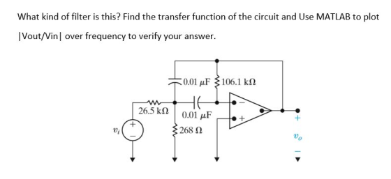
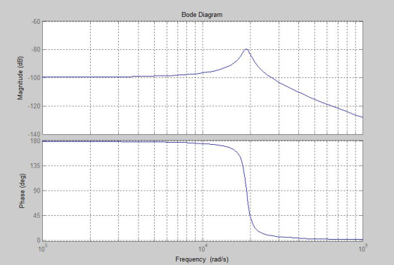
This filter is an active bandpass filter
Compute the transfer function for the circuit of in
terms of the circuit constants R1 R2 R3 C1 and C2. Then, replace
the complex variable with omega, and the circuit constants with
their numerical values and plot the magnitude versus radian
frequency .
Homework Answers


![1clear all: 2-num [-3773.5851: num-[-3773.585] den= [1 1885.0141 sys tf (num, den) 3.552362*10^8]; 5bode (sys) 6-grid on,;](http://img.homeworklib.com/images/97d4dd3f-0a9d-4acf-9db9-0ef30ff1817a.png?x-oss-process=image/resize,w_560)
In case you have any doubts or you did not understand any step please feel free to ask your doubts in the comments section. I would be happy to clarify it.
Add Answer to:
This filter is an active bandpass filter Compute the transfer function for the circuit of in term...
Design an active unity-gain bandpass filter with center frequency 750 Hz and bandwidtg 250 Hz and...
 Design an active unity-gain bandpass filter with
center frequency 750 Hz and bandwidtg 250 Hz and with 0.1 μF
capacitor, R1=6.4kΩ, R2=377Ω, and R3=12.7kΩ.
a)Discuss the circuit response with support of a Bode
magnitude plot.
b) Assume next that a load R_L is connected to the output of the
network at the terminal Vo(s). How does the frequency response of
the loaded configuration change?
c) Consider a broadband bandpass op amp filter with center
frequency 2.4 kHz and bandwidth 800...
Design an active unity-gain bandpass filter with
center frequency 750 Hz and bandwidtg 250 Hz and with 0.1 μF
capacitor, R1=6.4kΩ, R2=377Ω, and R3=12.7kΩ.
a)Discuss the circuit response with support of a Bode
magnitude plot.
b) Assume next that a load R_L is connected to the output of the
network at the terminal Vo(s). How does the frequency response of
the loaded configuration change?
c) Consider a broadband bandpass op amp filter with center
frequency 2.4 kHz and bandwidth 800...
Problem 3. Show that the circuit shown below behaves as a bandpass filter. (Hint-find the transfer...
 Problem 3. Show that the circuit shown below behaves as a bandpass filter. (Hint-find the transfer function for this circuit and show that it has the same form as the transfer function for a bandpass filter. a) Find he center frequency, bandwidth and gain for this bandpass filter. b) Find the cutoff frequencies and the quality for this bandpass filter 10 AF HA 400 SOLF
Hi everyone, I have a question about active filter, including a simulation, Please provide the sc...
 Hi everyone, I have a question about active filter, including a
simulation,
Please provide the screen capture.
Thanks.
5. Active Filter - III Consider the RC op-amp circuit shown in Fig. 5.4. Vin(t) is a sinusoidal signal with Vpp = 1 V, Rı = 10 ㏀ , R, = 20 ㏀ , and C,-C,-0.01 μF. Use Vcc-15V, The capacitors have zero initial energy stored. Ri 741 C1 C2 Volt) Fig. 5.5: Active filter - III (a) Find the transfer function...
Hi everyone, I have a question about active filter, including a
simulation,
Please provide the screen capture.
Thanks.
5. Active Filter - III Consider the RC op-amp circuit shown in Fig. 5.4. Vin(t) is a sinusoidal signal with Vpp = 1 V, Rı = 10 ㏀ , R, = 20 ㏀ , and C,-C,-0.01 μF. Use Vcc-15V, The capacitors have zero initial energy stored. Ri 741 C1 C2 Volt) Fig. 5.5: Active filter - III (a) Find the transfer function...
QUESTION #2 PLEASE 1. Derive the transfer function for the circuit shown below. Plot H(s) versus...
 QUESTION #2 PLEASE
1. Derive the transfer function for the circuit shown below. Plot H(s) versus frequency in Hertz, on a semilog scale. Ri 11.3 k Ri 22.6 k R R = 68.1 kN R3 C C 0.01 uF R2 Vout(s) Vin(s) C2 10 (s+5) H(s) = (s+100)(s5000) , (a) draw the magnitude Bode plot 2. For the transfer function and find the approximate maximum value of (H(jw) in dB, (b) find the value of w where 1 for w>5...
QUESTION #2 PLEASE
1. Derive the transfer function for the circuit shown below. Plot H(s) versus frequency in Hertz, on a semilog scale. Ri 11.3 k Ri 22.6 k R R = 68.1 kN R3 C C 0.01 uF R2 Vout(s) Vin(s) C2 10 (s+5) H(s) = (s+100)(s5000) , (a) draw the magnitude Bode plot 2. For the transfer function and find the approximate maximum value of (H(jw) in dB, (b) find the value of w where 1 for w>5...
Ri vo(t) = 0 Figure 19: Bandpass filter Use Matlab to plot the magnitude and phase...
 Ri vo(t) = 0 Figure 19: Bandpass filter Use Matlab to plot the magnitude and phase of the frequency response. Make sure the frequency range is wide enough to show enough details. Assume R1 = R2 = 1k1, C1 = 7.5nF, and C2 = 2.5uF.
Consider the following transfer function of a bandpass filter: 20 1,500 T(S) = 2 1,500 +...
 Consider the following transfer function of a bandpass filter: 20 1,500 T(S) = 2 1,500 + 1)(30.000 +1) a) Draw the Bode plot (magnitude and phase) of T(s). Label the slopes (dB/decade) b) Name the filter type. c) Determine the resonant frequency o d) Determine the gain in dB at the resonant frequency e) Determine bandwidth B, and the quality factor of the filter. Magnitude (dB) Phase (Deg)
Design a 5-tap FIR bandpass filter
Design a 5-tap FIR bandpass filter with a lower cutoff frequency of1,600 Hz, an upper cutoff frequency of 1,800 Hz, and a sampling rateof 8,000 Hz using a. rectangular window functionb. Hamming window function.Determine the transfer function and difference equation of the designedFIR system, and compute and plot the magnitude frequency responsefor Ω= 0, π/4, π/2, 3π/4, and π radians.PLEASE SHOW STEPS CLEARLY
The circuit shown in Figure 2 is called a lead-lag filter. a) Find the transfer function...
 The circuit shown in Figure 2 is called a lead-lag filter. a) Find the transfer function Vols)/Vis). Assume an ideal operational amplifier. b) Determine the partial fraction expansion for Vols)/V(s) c) Determine Volt) and plot the results. Comment on the response of the filter 3. C1 R2 C2 iSin looot RI M(s) Figure 2: Lead-Lag Filter
Using nodal analysis, calculate the transfer function of notch filter. Use the transfer function to calculate...
 Using nodal analysis, calculate the transfer function of notch
filter. Use the transfer function to calculate the expected gain
(using the actual resistor and capacitor values that were measured
for your experiment-See below). Hint: You need to solve the circuit
with nodal analysis, using the impedance of a capacitor as - j / (2
* pi * C). The amplifier at the end is just a unity gain amplifier
with a gain of 1, so it won't enter into the...
Using nodal analysis, calculate the transfer function of notch
filter. Use the transfer function to calculate the expected gain
(using the actual resistor and capacitor values that were measured
for your experiment-See below). Hint: You need to solve the circuit
with nodal analysis, using the impedance of a capacitor as - j / (2
* pi * C). The amplifier at the end is just a unity gain amplifier
with a gain of 1, so it won't enter into the...
Given the circuit below: R3 C1 Vout C2 R1 R3 Vin R2 ts 1 a) derive the transfer function between ...
 Given the circuit below: R3 C1 Vout C2 R1 R3 Vin R2 ts 1 a) derive the transfer function between the input and the output in terms of R1,C1,R2,C2 b) For this and all other parts below, assume Izl<Ipl, i..e that D(s) is a lead-type compensator. The transfer function is written in the following format ts 1 Express quantities K, z, p using R1,C1,R2,C2 Also, express Κα, α, τ using K,z, p c) Observe the values of s-jw on the...
 Design an active unity-gain bandpass filter with
center frequency 750 Hz and bandwidtg 250 Hz and with 0.1 μF
capacitor, R1=6.4kΩ, R2=377Ω, and R3=12.7kΩ.
a)Discuss the circuit response with support of a Bode
magnitude plot.
b) Assume next that a load R_L is connected to the output of the
network at the terminal Vo(s). How does the frequency response of
the loaded configuration change?
c) Consider a broadband bandpass op amp filter with center
frequency 2.4 kHz and bandwidth 800...
Design an active unity-gain bandpass filter with
center frequency 750 Hz and bandwidtg 250 Hz and with 0.1 μF
capacitor, R1=6.4kΩ, R2=377Ω, and R3=12.7kΩ.
a)Discuss the circuit response with support of a Bode
magnitude plot.
b) Assume next that a load R_L is connected to the output of the
network at the terminal Vo(s). How does the frequency response of
the loaded configuration change?
c) Consider a broadband bandpass op amp filter with center
frequency 2.4 kHz and bandwidth 800...
 Problem 3. Show that the circuit shown below behaves as a bandpass filter. (Hint-find the transfer function for this circuit and show that it has the same form as the transfer function for a bandpass filter. a) Find he center frequency, bandwidth and gain for this bandpass filter. b) Find the cutoff frequencies and the quality for this bandpass filter 10 AF HA 400 SOLF
 Hi everyone, I have a question about active filter, including a
simulation,
Please provide the screen capture.
Thanks.
5. Active Filter - III Consider the RC op-amp circuit shown in Fig. 5.4. Vin(t) is a sinusoidal signal with Vpp = 1 V, Rı = 10 ㏀ , R, = 20 ㏀ , and C,-C,-0.01 μF. Use Vcc-15V, The capacitors have zero initial energy stored. Ri 741 C1 C2 Volt) Fig. 5.5: Active filter - III (a) Find the transfer function...
Hi everyone, I have a question about active filter, including a
simulation,
Please provide the screen capture.
Thanks.
5. Active Filter - III Consider the RC op-amp circuit shown in Fig. 5.4. Vin(t) is a sinusoidal signal with Vpp = 1 V, Rı = 10 ㏀ , R, = 20 ㏀ , and C,-C,-0.01 μF. Use Vcc-15V, The capacitors have zero initial energy stored. Ri 741 C1 C2 Volt) Fig. 5.5: Active filter - III (a) Find the transfer function...
 QUESTION #2 PLEASE
1. Derive the transfer function for the circuit shown below. Plot H(s) versus frequency in Hertz, on a semilog scale. Ri 11.3 k Ri 22.6 k R R = 68.1 kN R3 C C 0.01 uF R2 Vout(s) Vin(s) C2 10 (s+5) H(s) = (s+100)(s5000) , (a) draw the magnitude Bode plot 2. For the transfer function and find the approximate maximum value of (H(jw) in dB, (b) find the value of w where 1 for w>5...
QUESTION #2 PLEASE
1. Derive the transfer function for the circuit shown below. Plot H(s) versus frequency in Hertz, on a semilog scale. Ri 11.3 k Ri 22.6 k R R = 68.1 kN R3 C C 0.01 uF R2 Vout(s) Vin(s) C2 10 (s+5) H(s) = (s+100)(s5000) , (a) draw the magnitude Bode plot 2. For the transfer function and find the approximate maximum value of (H(jw) in dB, (b) find the value of w where 1 for w>5...
 Ri vo(t) = 0 Figure 19: Bandpass filter Use Matlab to plot the magnitude and phase of the frequency response. Make sure the frequency range is wide enough to show enough details. Assume R1 = R2 = 1k1, C1 = 7.5nF, and C2 = 2.5uF.
 Consider the following transfer function of a bandpass filter: 20 1,500 T(S) = 2 1,500 + 1)(30.000 +1) a) Draw the Bode plot (magnitude and phase) of T(s). Label the slopes (dB/decade) b) Name the filter type. c) Determine the resonant frequency o d) Determine the gain in dB at the resonant frequency e) Determine bandwidth B, and the quality factor of the filter. Magnitude (dB) Phase (Deg)
 The circuit shown in Figure 2 is called a lead-lag filter. a) Find the transfer function Vols)/Vis). Assume an ideal operational amplifier. b) Determine the partial fraction expansion for Vols)/V(s) c) Determine Volt) and plot the results. Comment on the response of the filter 3. C1 R2 C2 iSin looot RI M(s) Figure 2: Lead-Lag Filter
 Using nodal analysis, calculate the transfer function of notch
filter. Use the transfer function to calculate the expected gain
(using the actual resistor and capacitor values that were measured
for your experiment-See below). Hint: You need to solve the circuit
with nodal analysis, using the impedance of a capacitor as - j / (2
* pi * C). The amplifier at the end is just a unity gain amplifier
with a gain of 1, so it won't enter into the...
Using nodal analysis, calculate the transfer function of notch
filter. Use the transfer function to calculate the expected gain
(using the actual resistor and capacitor values that were measured
for your experiment-See below). Hint: You need to solve the circuit
with nodal analysis, using the impedance of a capacitor as - j / (2
* pi * C). The amplifier at the end is just a unity gain amplifier
with a gain of 1, so it won't enter into the...
 Given the circuit below: R3 C1 Vout C2 R1 R3 Vin R2 ts 1 a) derive the transfer function between the input and the output in terms of R1,C1,R2,C2 b) For this and all other parts below, assume Izl<Ipl, i..e that D(s) is a lead-type compensator. The transfer function is written in the following format ts 1 Express quantities K, z, p using R1,C1,R2,C2 Also, express Κα, α, τ using K,z, p c) Observe the values of s-jw on the...
Most questions answered within 3 hours.
-
Where is the error in this code sequence?
String s1 = "Hello";
String s2 = "ello";...
asked 11 months ago -
Financial data for Joel de Paris, Inc., for last year
follow:
Joel de Paris, Inc.
Balance...
asked 11 months ago -
Consider this reaction:
Al2(SO4)3 (aq)+ BaCl3
(aq) Al2Cl6 (aq)- +
3BaSO4(s) . What is the...
asked 11 months ago -
Suppose that Savneet is considering increasing her
recent random sample from 20 car rentals to 40...
asked 11 months ago -
Trucks arrive at an unloading terminal at an average rate of 120
per hour.
Trucks arrive...
asked 11 months ago -
Why are methanol and ethanol completely soluble in water while
octanol is not very little soluble....
asked 11 months ago -
A facilities manager at a university reads in a research report
that the mean amount of...
asked 11 months ago -
When the CuSO4 is rehydrated by adding water to the anhydrous
compound, is this an endothermic...
asked 11 months ago -
A ray of sunlight is passing from diamond into crown glass; the
angle of incidence is...
asked 11 months ago -
A block of mass 0.249 kg is placed on top of a light, vertical
spring of...
asked 11 months ago -
how do the kidneys compensate in the presences of acidosis
a) trigger hyperventilate
b) reserve acid...
asked 11 months ago -
Question 501 pts
The rental rate of capital to the firm increases. Which of the
following...
asked 11 months ago