Please explain to me how the following arduino code control the
smart home system design below.
#include "ESP8266.h"
#include <Wire.h>
#include <LiquidCrystal_I2C.h>
#include <dht.h>
#define DATA_PIN 2
#define SSID "abc"
#define PASSWORD "12345678"
byte termometerLogo[8] =
{
B00100,
B01010,
B01010,
B01110,
B01110,
B11111,
B11111,
B01110
};
byte humidityLogo[8] =
{
B00100,
B00100,
B01010,
B01010,
B10001,
B10001,
B10001,
B01110,
};
SoftwareSerial mySerial(10,11);
ESP8266 wifi(mySerial);
LiquidCrystal_I2C lcd(0x27, 2, 1, 0, 4, 5, 6, 7, 3, POSITIVE);
dht DHT;
char buffData[150];
const int pinRelay1=3;
const int pinRelay2=4;
const int pinPir=6;
const int pinGas=5;
boolean notif;
boolean light=false,fan=false;
void setup(void)
{
lcd.begin(16,2);
pinMode(pinRelay1,OUTPUT);//light
pinMode(pinRelay2,OUTPUT);//fan
digitalWrite(pinRelay1,HIGH);
digitalWrite(pinRelay2,HIGH);
pinMode(pinPir,INPUT);
pinMode(pinGas,INPUT);
lcd.backlight();
delay(250);
lcd.noBacklight();
delay(250);
lcd.backlight();
lcd.clear();
lcd.createChar(1,termometerLogo);
lcd.createChar(2,humidityLogo);
lcd.setCursor(0,0);
lcd.print(" SMART HOME ");
lcd.setCursor(0,1);
lcd.print(" SYSTEM ");
wifi.setOprToStation();
if (wifi.joinAP(SSID, PASSWORD)) {
lcd.clear();
lcd.setCursor(0,0);
lcd.print("Join Net OK");
} else {
lcd.clear();
lcd.setCursor(0,0);
lcd.print("Join Net Fail");
}
delay(2000);
lcd.clear();
}
boolean updatenotif=false;
void loop(void)
{
int readData = DHT.read22(DATA_PIN);
float t = DHT.temperature;
float h = DHT.humidity;
int statusPir=digitalRead(pinPir);
int statusGas=digitalRead(pinGas);
if(!statusGas){
if(!updatenotif) notif=true;
updatenotif=true;
}else{
notif=false;
updatenotif=false;
}
lcd.setCursor(0, 0);
lcd.write(1);
lcd.setCursor(1, 0);
lcd.print((float)DHT.temperature, 2);
lcd.setCursor(6, 0);
lcd.print((char)223);
lcd.print("C");
lcd.setCursor(9, 0);
lcd.write(2);
lcd.setCursor(10, 0);
lcd.print((float)DHT.humidity, 2);
lcd.print("%");
if(DHT.temperature>27){
fan=true;
digitalWrite(pinRelay2,LOW); //pir temp to fan
}else{
fan=false; // relay active low
digitalWrite(pinRelay2,HIGH);
}
if(statusPir){
light=true;
digitalWrite(pinRelay1,LOW); //PIR sensor to light
}else{
light=false;
digitalWrite(pinRelay1,HIGH);
}
lcd.setCursor(0, 1);
if(statusPir){
lcd.print("ACTIVE");
}else{
lcd.print("PASSIVE");
}
lcd.setCursor(8, 1);
if(!statusGas){
lcd.print("DANGER");
}else{
lcd.print("NORMAL");
}
if (wifi.createTCP("lab-android.com", 80)) {
} else {
}
sprintf(buffData,"GET /abcde/mail.php?t=%d&h=%d&g=%d&p=%d&n=%d&l=%d&f=%d HTTP/1.1\r\nHost: www.lab-online.com\r\nConnection: close\r\n\r\n",int(t),int(h),statusGas,statusPir,notif,light,fan);
wifi.send((const uint8_t*)buffData, strlen(buffData));
if (wifi.releaseTCP()) {
notif=false;
} else {
}
lcd.clear();
}
Homework Answers
Above all are arduino program to setup he device here " # define" is a syntax : use to set constants for compiling in arduino and "#include" also syntax: used to include the libraries objects of those components. such as lcd and pir. This is the program for remote controlling of temperature.
SoftwareSerial mySerial(10,11); // this defines RX and TX
ESP8266 wifi(mySerial); // reading wifi data connected to these pins
LiquidCrystal_I2C lcd(0x27, 2, 1, 0, 4, 5, 6, 7, 3, POSITIVE); // calling LCD pins
dht DHT; // humidity and temperature sensor
char buffData[150]; //storing index pointed by buffer
const int pinRelay1=3; //setting relay
const int pinRelay2=4;
const int pinPir=6; // setting Pir value
const int pinGas=5;
boolean notif; // data structure : true or false
boolean light=false,fan=false; // is it light and fan on? set = false
void setup(void)
{
lcd.begin(16,2); // if false the boolean string hen lcd pin 16,2 get info
pinMode(pinRelay1,OUTPUT);//light
pinMode(pinRelay2,OUTPUT);//fan
digitalWrite(pinRelay1,HIGH); // turn on ligh
digitalWrite(pinRelay2,HIGH); // turn on fan
pinMode(pinPir,INPUT); // asking pir
pinMode(pinGas,INPUT);
lcd.backlight();
delay(250); // lcd delay time set
lcd.noBacklight();
delay(250);
lcd.backlight();
lcd.clear();
lcd.createChar(1,termometerLogo); // lcd shows or initiate thermometer
lcd.createChar(2,humidityLogo);
lcd.setCursor(0,0); // curser at initial position
lcd.print(" SMART HOME "); // displays smart home on screen
lcd.setCursor(0,1); // curser moves 1 pixel y-coordinate
lcd.print(" SYSTEM "); display system on screen
wifi.setOprToStation(); // calling wifi
if (wifi.joinAP(SSID, PASSWORD)) { // decision structure wifi ssid and password
lcd.clear();
lcd.setCursor(0,0);
lcd.print("Join Net OK"); // display net ok on screen
} else { // decision structue: if false "wifi is not ok" do this operation
lcd.clear();
lcd.setCursor(0,0);
lcd.print("Join Net Fail"); // show net fail on screen
}
delay(2000);
lcd.clear();
}
boolean updatenotif=false; // bollean value updating set false
void loop(void)
{
int readData = DHT.read22(DATA_PIN); // read the value of humidity sensor
float t = DHT.temperature; // temperature valve data in DHT
float h = DHT.humidity; // humidity value in DHT
int statusPir=digitalRead(pinPir); // read status of PIR sensor
int statusGas=digitalRead(pinGas); // and Gas
if(!statusGas){ // using ! = not ( it show true as false) operator ; reading status of gas
if(!updatenotif) notif=true; // if false set as true; here used not operator
updatenotif=true; // uodate as true
}else{ // otherwise means false
notif=false;
updatenotif=false; // then update as false
}
lcd.setCursor(0, 0);
lcd.write(1); // write data
lcd.setCursor(1, 0);
lcd.print((float)DHT.temperature, 2); // display DHT temperature in real number
lcd.setCursor(6, 0); // move x-position to 6
lcd.print((char)223); // display the degree
lcd.print("C"); // and C ; hear above and this command lines are to show centigrade
lcd.setCursor(9, 0);
lcd.write(2);
lcd.setCursor(10, 0);
lcd.print((float)DHT.humidity, 2); // display humidity
lcd.print("%"); / in percentage
if(DHT.temperature>27){ // comparision operator if temp > 27 true
fan=true; // fan set to on
digitalWrite(pinRelay2,LOW); //pir temp to fan // set relayy 2:: low means off the fan
}else{ // otherwise
fan=false; // relay active low :: fan set off
digitalWrite(pinRelay2,HIGH); // turn it on
}
if(statusPir){ // reading pir status
light=true; // light is on
digitalWrite(pinRelay1,LOW); //PIR sensor to light:; then off it
}else{
light=false;
digitalWrite(pinRelay1,HIGH); // otherwise turn it on
}
lcd.setCursor(0, 1);
if(statusPir){ // asking pir status
lcd.print("ACTIVE"); // display active
}else{ // otherwise
lcd.print("PASSIVE"); // show as passive or off
}
lcd.setCursor(8, 1);
if(!statusGas){ // read gas and used not operator
lcd.print("DANGER"); // display danger
}else{
lcd.print("NORMAL"); // otherwise shows as normal
}
if (wifi.createTCP("lab-android.com", 80)) { // create protocal b/w port and lab-android.com
} else { // otherwise
}
sprintf(buffData,"GET /abcde/mail.php?t=%d&h=%d&g=%d&p=%d&n=%d&l=%d&f=%d HTTP/1.1\r\nHost: www.lab-online.com\r\nConnection: close\r\n\r\n",int(t),int(h),statusGas,statusPir,notif,light,fan);
wifi.send((const uint8_t*)buffData, strlen(buffData)); /// ruun the buffering path and code; it sends data to host website through wifi communication path
if (wifi.releaseTCP()) { // if tcp off
notif=false; // notify it
} else {
}
lcd.clear(); //clear all values of lcd; reset
}
Add Answer to:
Please explain to me how the following arduino code control the smart home system design below. #...
Please explain how the smart home system circuit design below is connected and designed. The smar...
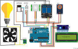 Please explain how the smart home system circuit design below is
connected and designed. The smart home will be able to automatic
on/off light through motion sensor, automatic on/off fan after
reaching 27 degree, send email when detect smoke. The bulb was
changed into a LED which is connected directly to the relay instead
of parallel with the fan.
PIR MQ-2 ESP8266 DHT22 13S Arduino LCD Karakter 16x2 AC Socket fritzing
PIR MQ-2 ESP8266 DHT22 13S Arduino LCD Karakter 16x2...
Please explain how the smart home system circuit design below is
connected and designed. The smart home will be able to automatic
on/off light through motion sensor, automatic on/off fan after
reaching 27 degree, send email when detect smoke. The bulb was
changed into a LED which is connected directly to the relay instead
of parallel with the fan.
PIR MQ-2 ESP8266 DHT22 13S Arduino LCD Karakter 16x2 AC Socket fritzing
PIR MQ-2 ESP8266 DHT22 13S Arduino LCD Karakter 16x2...
I'm trying to make a circuit from this code that I found for a personal project,...
I'm trying to make a circuit from this code that I found for a personal project, but I'm having trouble figuring it out. Could someone make me a Circuit Diagram for this code with an LED, Servo, and Arduino Nano on BreadBoard. (No Battery, just use usb power from Nano) Thank You. Nano Code: const int servoPin = 5; const int buttonPin = 3; const int LEDPin = 4; #include <Servo.h> Servo visorServo; void setup() { visorServo.write(0); // Initial position...
In the code below i am using a LS-3006 SERVO on the arduino uno and everytime...
In the code below i am using a LS-3006 SERVO on the arduino uno and everytime i hit the pushbutton to input a time the servo comes on. Would anyone be able to tell me what a solution is to this problem? Thanks #include <Wire.h> #include <DS3231.h> #include <Servo.h> #include <LiquidCrystal.h> #include <Keypad.h> const byte ROWS = 4; // # of rows const byte COLS = 4; // # of columns // Define the Keymap char keys[ROWS][COLS] = { {'1','2','3','A'},...
Need help in filling the missing lines in the program template provided down below. (Arduino Uno)....
Need help in filling the missing lines in the program template provided down below. (Arduino Uno). Using the program template provided, fill in the missing lines in the program which increments an unsigned integer variable when the “pin 2” button is pressed and decrements an unsigned integer variable when the “pin 3” button is pressed. Your program must display the integer variable (modulo 8) on the 7-segment LED display you designed in the previous lab. Once again you should be...
14. 10 pts. You have the following code lines in an Arduino c++ sketch to blink an LED and control a standard servo (not a continuous servo) and buzzer: #include <Servo.h> Servo frontSer...
 14. 10 pts. You have the following code lines in an Arduino c++ sketch to blink an LED and control a standard servo (not a continuous servo) and buzzer: #include <Servo.h> Servo frontServo; int time 2500; int multiple 3; int leg-5 int red 2; void setup()X pinMode(red,OUTPUT) frontServo.attach(leg): pinMode(4, OUTPUT) void looplf frontServo.write(0); digitalWrite(red, HIGH); delay(time); tone(4,400,500); digitalWrite(red,LOW); time-time"multiple; delay(time); Answer the following: What pin should the LED be connected to? what pin should the information lead wire of the...
Design a circuit and Arduino program that accomplishes the following: An IR distance sensor will detect the presence (t...
Design a circuit and Arduino program that accomplishes the following: An IR distance sensor will detect the presence (through waving of a hand) A H-Bridge circuit with 9V battery power will control the direction of the DC motor as described in Chapter 4 (pp. 70-79) of your textbook. When a hand is waved over the IR sensor, the motor moves in one direction (simulating opening a door). There is a 2 second pause, and then the motor moves in the...
I am doing an Arduino Uno project where I made a "Simon says" memory game with 3 neopixel LED str...
I am doing an Arduino Uno project where I made a "Simon says" memory game with 3 neopixel LED strips and 3 - ultrasonics. I have them working independently but I need to combine the code so they work together. Here is what I have: Memory Game #define PLAYER_WAIT_TIME 2000 // The time allowed between button presses - 2s byte sequence[100]; // Storage for the light sequence byte curLen = 0; // Current length of the sequence byte inputCount =...
I am unsure how to add the following methods onto this code?? please help - rowValuesIncrease(int[][]...
I am unsure how to add the following methods onto this code?? please help - rowValuesIncrease(int[][] t) A method that returns true if from left to right in any row, the integers are increasing, otherwise false. - columnValuesIncrease(int[][] t) A method that returns true if from top to bottom in any column, the integers are increasing, otherwise false. - isSetOf1toN(int[][] t) A method that returns true if the set of integers used is {1, 2, . . . , n}...
Please help with my car traffic simulator! Code that I already have below, I do not know how to...
 Please help with my car traffic simulator!
Code that I already have below, I do not know how to start it
off!
public class IntersectionSimulation
{
private final static int EAST_WEST_GREEN_TIME = 30 ;
private final static int[] NORTH_SOUTH_GREEN_TIMES = { 20, 24, 30, 42 } ;
private final static int[] CAR_INTERSECTION_RATES = { 3, 5, 10 } ;
private final static int[] CAR_QUEUEING_RATES = { 5, 10, 30 } ;
private final static int[] EXPERIMENT_DURATIONS = { 3*60, 5*60,...
Please help with my car traffic simulator!
Code that I already have below, I do not know how to start it
off!
public class IntersectionSimulation
{
private final static int EAST_WEST_GREEN_TIME = 30 ;
private final static int[] NORTH_SOUTH_GREEN_TIMES = { 20, 24, 30, 42 } ;
private final static int[] CAR_INTERSECTION_RATES = { 3, 5, 10 } ;
private final static int[] CAR_QUEUEING_RATES = { 5, 10, 30 } ;
private final static int[] EXPERIMENT_DURATIONS = { 3*60, 5*60,...
 Please explain how the smart home system circuit design below is
connected and designed. The smart home will be able to automatic
on/off light through motion sensor, automatic on/off fan after
reaching 27 degree, send email when detect smoke. The bulb was
changed into a LED which is connected directly to the relay instead
of parallel with the fan.
PIR MQ-2 ESP8266 DHT22 13S Arduino LCD Karakter 16x2 AC Socket fritzing
PIR MQ-2 ESP8266 DHT22 13S Arduino LCD Karakter 16x2...
Please explain how the smart home system circuit design below is
connected and designed. The smart home will be able to automatic
on/off light through motion sensor, automatic on/off fan after
reaching 27 degree, send email when detect smoke. The bulb was
changed into a LED which is connected directly to the relay instead
of parallel with the fan.
PIR MQ-2 ESP8266 DHT22 13S Arduino LCD Karakter 16x2 AC Socket fritzing
PIR MQ-2 ESP8266 DHT22 13S Arduino LCD Karakter 16x2...
 14. 10 pts. You have the following code lines in an Arduino c++ sketch to blink an LED and control a standard servo (not a continuous servo) and buzzer: #include <Servo.h> Servo frontServo; int time 2500; int multiple 3; int leg-5 int red 2; void setup()X pinMode(red,OUTPUT) frontServo.attach(leg): pinMode(4, OUTPUT) void looplf frontServo.write(0); digitalWrite(red, HIGH); delay(time); tone(4,400,500); digitalWrite(red,LOW); time-time"multiple; delay(time); Answer the following: What pin should the LED be connected to? what pin should the information lead wire of the...
 Please help with my car traffic simulator!
Code that I already have below, I do not know how to start it
off!
public class IntersectionSimulation
{
private final static int EAST_WEST_GREEN_TIME = 30 ;
private final static int[] NORTH_SOUTH_GREEN_TIMES = { 20, 24, 30, 42 } ;
private final static int[] CAR_INTERSECTION_RATES = { 3, 5, 10 } ;
private final static int[] CAR_QUEUEING_RATES = { 5, 10, 30 } ;
private final static int[] EXPERIMENT_DURATIONS = { 3*60, 5*60,...
Please help with my car traffic simulator!
Code that I already have below, I do not know how to start it
off!
public class IntersectionSimulation
{
private final static int EAST_WEST_GREEN_TIME = 30 ;
private final static int[] NORTH_SOUTH_GREEN_TIMES = { 20, 24, 30, 42 } ;
private final static int[] CAR_INTERSECTION_RATES = { 3, 5, 10 } ;
private final static int[] CAR_QUEUEING_RATES = { 5, 10, 30 } ;
private final static int[] EXPERIMENT_DURATIONS = { 3*60, 5*60,...
Most questions answered within 3 hours.
-
Where is the error in this code sequence?
String s1 = "Hello";
String s2 = "ello";...
asked 11 months ago -
Financial data for Joel de Paris, Inc., for last year
follow:
Joel de Paris, Inc.
Balance...
asked 11 months ago -
Consider this reaction:
Al2(SO4)3 (aq)+ BaCl3
(aq) Al2Cl6 (aq)- +
3BaSO4(s) . What is the...
asked 11 months ago -
Suppose that Savneet is considering increasing her
recent random sample from 20 car rentals to 40...
asked 11 months ago -
Trucks arrive at an unloading terminal at an average rate of 120
per hour.
Trucks arrive...
asked 11 months ago -
Why are methanol and ethanol completely soluble in water while
octanol is not very little soluble....
asked 11 months ago -
A facilities manager at a university reads in a research report
that the mean amount of...
asked 11 months ago -
When the CuSO4 is rehydrated by adding water to the anhydrous
compound, is this an endothermic...
asked 11 months ago -
A ray of sunlight is passing from diamond into crown glass; the
angle of incidence is...
asked 11 months ago -
A block of mass 0.249 kg is placed on top of a light, vertical
spring of...
asked 11 months ago -
how do the kidneys compensate in the presences of acidosis
a) trigger hyperventilate
b) reserve acid...
asked 11 months ago -
Question 501 pts
The rental rate of capital to the firm increases. Which of the
following...
asked 11 months ago