
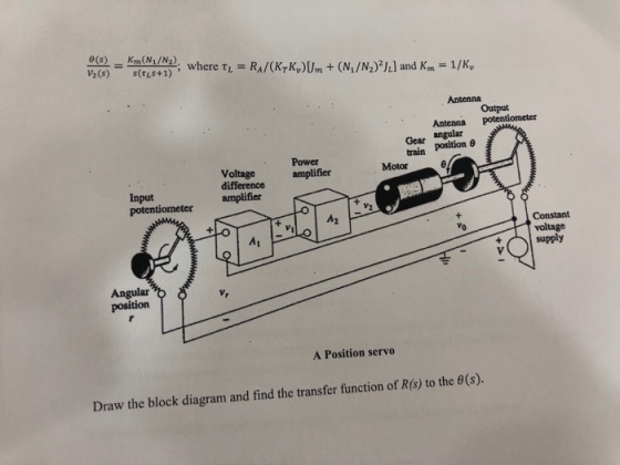
½(s) s(TLS+1) Output Antenna potentiometer Gear angular train position θ Power difference amplifier amplifier Motor Input potentiometer Vo voltage supply Angular position A Position servo Draw the block diagram and find the transfer function of R(s) to the θ(s).
Homework Answers
Add Answer to:
A simple but practical feedback control system is shown below. It is a positioning system or posi...
Control Lab
 Obtain the Simulink diagram of position control system shown in figure 1 and run the simulation. Assume the following numerical values for system constants:r = angular displacement of reference input shaft, radiansc = angular displacement of the output shaft, radiansθ = angular displacement of the motor shaft, radiansk1 = gain of the potentiometer error detector = 24/π volt/radkp = amplifier gain = 10 volt/voltea = applied armature voltage, volteb = back emf, voltRa = armature resistance, ohmsLa = armature winding...
control system System Description: The figure 1 and 2 below show, respectively, components and block diagram...
 control system
System Description: The figure 1 and 2 below show, respectively, components and block diagram of a motor and the measurements of velocity (via the tacho unit) and position (via the potentiometer). n represents the gearbox ratio between the rotating shaft and the output shaft. The left-hand side of the diagram represents the controller. A reference set point for the rotating shaft is entered in degrees and this is equivalent voltage. The error is calculated by subtracting the measured...
control system
System Description: The figure 1 and 2 below show, respectively, components and block diagram of a motor and the measurements of velocity (via the tacho unit) and position (via the potentiometer). n represents the gearbox ratio between the rotating shaft and the output shaft. The left-hand side of the diagram represents the controller. A reference set point for the rotating shaft is entered in degrees and this is equivalent voltage. The error is calculated by subtracting the measured...
D.C. motor is shown below, where the inductance L and the resistance R model the armature circuit. The voltage Vbrepresents the back-emf which is proportional to dθ/dt via Kf. The torque T generated b...
 D.C. motor is shown below, where the inductance
L and the resistance R model the
armature circuit. The voltage
Vbrepresents the back-emf
which is proportional to dθ/dt via
Kf. The torque T
generated by the motor is proportional to the
i via a constant
Kt. In this application, let the
constants Kt =
Kf. The inertia
Jrepresents the combined inertia of the motor and
load. The viscous friction acting on the output shaft is
b. Attached to the shaft is...
D.C. motor is shown below, where the inductance
L and the resistance R model the
armature circuit. The voltage
Vbrepresents the back-emf
which is proportional to dθ/dt via
Kf. The torque T
generated by the motor is proportional to the
i via a constant
Kt. In this application, let the
constants Kt =
Kf. The inertia
Jrepresents the combined inertia of the motor and
load. The viscous friction acting on the output shaft is
b. Attached to the shaft is...
Q 1- 08 Pts) Figure below is a diagram of a DC motor connected in parnllel to a current source i,...
 Q 1- 08 Pts) Figure below is a diagram of a DC motor connected in parnllel to a current source i,. The torque and back-EMF constants of the motor are Ko K respectively, the motor resistance is R, also modeled as connected in parallel, the motor inertia is 1- (not shown), and the motor inductance is negligible. The motor load is an inertia J with compliance (stiffness) K and viscous friction coefficient b, and it is attached a gear pair...
01- (08 Pts) Figure below is a diagram of a DC motor connected in parallel to...
 01- (08 Pts) Figure below is a diagram of a DC motor connected in parallel to a current source is the torque and back-EMF constants of the motor are K. K respectively, the motor resistance is R, also modeled as connected in parallel, the motor inertia is I. (not shown), and the motor inductance is negligible. The motor load is an inertia compliance (stiffness) K and viscous friction coefficient b, and it is attached to the motor via a gear...
D.C. motor is shown below, where the inductance L and the resistance R model the armature...
 D.C. motor is shown below, where the inductance
L and the resistance R model the
armature circuit. The voltage
Vbrepresents the back-emf
which is proportional to dθ/dt via
Kf. The torque T
generated by the motor is proportional to the
i via a constant
Kt. In this application, let the
constants Kt =
Kf. The inertia J
represents the combined inertia of the motor and load. The viscous
friction acting on the output shaft is b. Attached
to the shaft...
D.C. motor is shown below, where the inductance
L and the resistance R model the
armature circuit. The voltage
Vbrepresents the back-emf
which is proportional to dθ/dt via
Kf. The torque T
generated by the motor is proportional to the
i via a constant
Kt. In this application, let the
constants Kt =
Kf. The inertia J
represents the combined inertia of the motor and load. The viscous
friction acting on the output shaft is b. Attached
to the shaft...
(30 pts) A D.C. motor is shown below, where the inductance L and the resistance R model the armat...
 (30 pts) A D.C. motor is shown below, where the inductance L and the resistance R model the armature circuit. The voltage Vb represents the back-emf which is proportional to dθ/dt via K. The torque T generated by the motor is proportional to the i via a constant K. The inertia J represents the combined inertia of the motor and load. The viscous friction acting on the output shaft is B 1. pur voltaop a. A. (10 pts) Find the...
In the gear train shown below, the pinion 2 is the driver, and gear 5 is...
 In the gear train shown below, the pinion 2 is the driver, and gear 5 is the output gear. All gears are spur gears has a module of 2.5mm and pressure angle of 200. The number of gear teeth are: N2 - 14, N3 - 84, N4 - 14, N5 - 70 teeth. The gear set transmits the power of 1.5KW at a constant angular velocity of XX rev/min. Where XX is the last two digits of your University ID...
3.3 Consider the positional servomechanism shown in Fig. P3.3. Assume that the input to the system...
 3.3 Consider the positional servomechanism shown in Fig. P3.3. Assume that the input to the system is reference shaft position ®, and the system output is the load shaft position 0. Draw a block diagram of the system indicating the transfer function of each block. Simplify the block diagram to obtain (s)/e (s). The parameters of the system are given below. Sensitivity of error detector K = 10 volts/rad Amplifier gain K = 50 volts/volt Motor field resistance R,= 100...
3.2 Pre-Lab Assignment When deriving the governing equations for an electromechanical system, it is often beneficial...
 3.2 Pre-Lab Assignment When deriving the governing equations for an electromechanical system, it is often beneficial to examine the electrical and mechanical components independently. Looking at only the electrical components of the QUBE-Servo DC motor (as shown in Figure 3.2): R v00 C e, (00 Figure 3.2: Electrical curcuit of the QUBE-Servo DC motor Q1. Write the differential equation in the form of Kirchoff's voltage law) in the Laplace domain for the electrical circuit (do not use parameter values given...
 control system
System Description: The figure 1 and 2 below show, respectively, components and block diagram of a motor and the measurements of velocity (via the tacho unit) and position (via the potentiometer). n represents the gearbox ratio between the rotating shaft and the output shaft. The left-hand side of the diagram represents the controller. A reference set point for the rotating shaft is entered in degrees and this is equivalent voltage. The error is calculated by subtracting the measured...
control system
System Description: The figure 1 and 2 below show, respectively, components and block diagram of a motor and the measurements of velocity (via the tacho unit) and position (via the potentiometer). n represents the gearbox ratio between the rotating shaft and the output shaft. The left-hand side of the diagram represents the controller. A reference set point for the rotating shaft is entered in degrees and this is equivalent voltage. The error is calculated by subtracting the measured...
 D.C. motor is shown below, where the inductance
L and the resistance R model the
armature circuit. The voltage
Vbrepresents the back-emf
which is proportional to dθ/dt via
Kf. The torque T
generated by the motor is proportional to the
i via a constant
Kt. In this application, let the
constants Kt =
Kf. The inertia
Jrepresents the combined inertia of the motor and
load. The viscous friction acting on the output shaft is
b. Attached to the shaft is...
D.C. motor is shown below, where the inductance
L and the resistance R model the
armature circuit. The voltage
Vbrepresents the back-emf
which is proportional to dθ/dt via
Kf. The torque T
generated by the motor is proportional to the
i via a constant
Kt. In this application, let the
constants Kt =
Kf. The inertia
Jrepresents the combined inertia of the motor and
load. The viscous friction acting on the output shaft is
b. Attached to the shaft is...
 Q 1- 08 Pts) Figure below is a diagram of a DC motor connected in parnllel to a current source i,. The torque and back-EMF constants of the motor are Ko K respectively, the motor resistance is R, also modeled as connected in parallel, the motor inertia is 1- (not shown), and the motor inductance is negligible. The motor load is an inertia J with compliance (stiffness) K and viscous friction coefficient b, and it is attached a gear pair...
 01- (08 Pts) Figure below is a diagram of a DC motor connected in parallel to a current source is the torque and back-EMF constants of the motor are K. K respectively, the motor resistance is R, also modeled as connected in parallel, the motor inertia is I. (not shown), and the motor inductance is negligible. The motor load is an inertia compliance (stiffness) K and viscous friction coefficient b, and it is attached to the motor via a gear...
 D.C. motor is shown below, where the inductance
L and the resistance R model the
armature circuit. The voltage
Vbrepresents the back-emf
which is proportional to dθ/dt via
Kf. The torque T
generated by the motor is proportional to the
i via a constant
Kt. In this application, let the
constants Kt =
Kf. The inertia J
represents the combined inertia of the motor and load. The viscous
friction acting on the output shaft is b. Attached
to the shaft...
D.C. motor is shown below, where the inductance
L and the resistance R model the
armature circuit. The voltage
Vbrepresents the back-emf
which is proportional to dθ/dt via
Kf. The torque T
generated by the motor is proportional to the
i via a constant
Kt. In this application, let the
constants Kt =
Kf. The inertia J
represents the combined inertia of the motor and load. The viscous
friction acting on the output shaft is b. Attached
to the shaft...
 (30 pts) A D.C. motor is shown below, where the inductance L and the resistance R model the armature circuit. The voltage Vb represents the back-emf which is proportional to dθ/dt via K. The torque T generated by the motor is proportional to the i via a constant K. The inertia J represents the combined inertia of the motor and load. The viscous friction acting on the output shaft is B 1. pur voltaop a. A. (10 pts) Find the...
 In the gear train shown below, the pinion 2 is the driver, and gear 5 is the output gear. All gears are spur gears has a module of 2.5mm and pressure angle of 200. The number of gear teeth are: N2 - 14, N3 - 84, N4 - 14, N5 - 70 teeth. The gear set transmits the power of 1.5KW at a constant angular velocity of XX rev/min. Where XX is the last two digits of your University ID...
 3.3 Consider the positional servomechanism shown in Fig. P3.3. Assume that the input to the system is reference shaft position ®, and the system output is the load shaft position 0. Draw a block diagram of the system indicating the transfer function of each block. Simplify the block diagram to obtain (s)/e (s). The parameters of the system are given below. Sensitivity of error detector K = 10 volts/rad Amplifier gain K = 50 volts/volt Motor field resistance R,= 100...
 3.2 Pre-Lab Assignment When deriving the governing equations for an electromechanical system, it is often beneficial to examine the electrical and mechanical components independently. Looking at only the electrical components of the QUBE-Servo DC motor (as shown in Figure 3.2): R v00 C e, (00 Figure 3.2: Electrical curcuit of the QUBE-Servo DC motor Q1. Write the differential equation in the form of Kirchoff's voltage law) in the Laplace domain for the electrical circuit (do not use parameter values given...
Most questions answered within 3 hours.
-
Where is the error in this code sequence?
String s1 = "Hello";
String s2 = "ello";...
asked 11 months ago -
Financial data for Joel de Paris, Inc., for last year
follow:
Joel de Paris, Inc.
Balance...
asked 11 months ago -
Consider this reaction:
Al2(SO4)3 (aq)+ BaCl3
(aq) Al2Cl6 (aq)- +
3BaSO4(s) . What is the...
asked 11 months ago -
Suppose that Savneet is considering increasing her
recent random sample from 20 car rentals to 40...
asked 11 months ago -
Trucks arrive at an unloading terminal at an average rate of 120
per hour.
Trucks arrive...
asked 11 months ago -
Why are methanol and ethanol completely soluble in water while
octanol is not very little soluble....
asked 11 months ago -
A facilities manager at a university reads in a research report
that the mean amount of...
asked 11 months ago -
When the CuSO4 is rehydrated by adding water to the anhydrous
compound, is this an endothermic...
asked 11 months ago -
A ray of sunlight is passing from diamond into crown glass; the
angle of incidence is...
asked 11 months ago -
A block of mass 0.249 kg is placed on top of a light, vertical
spring of...
asked 11 months ago -
how do the kidneys compensate in the presences of acidosis
a) trigger hyperventilate
b) reserve acid...
asked 11 months ago -
Question 501 pts
The rental rate of capital to the firm increases. Which of the
following...
asked 11 months ago