
Homework Answers

Add Answer to:
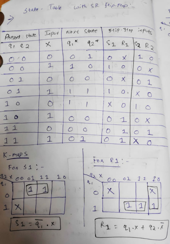
1) For the following state table, design the system using SR flip flops. 0 0 1 10 01 10 11 0o 01 0
4. For the following state table 00 11 01 01 00 1 1 01 11 jus Design the system using a T flip flop for q, and an SR flip flop for the equations for the flip flop inputs and the output. 4. F...
 4. For the following state table 00 11 01 01 00 1 1 01 11 jus Design the system using a T flip flop for q, and an SR flip flop for the equations for the flip flop inputs and the output.
4. For the following state table 00 11 01 01 00 1 1 01 11 jus Design the system using a T flip flop for q, and an SR flip flop for the equations for the flip flop...
4. For the following state table 00 11 01 01 00 1 1 01 11 jus Design the system using a T flip flop for q, and an SR flip flop for the equations for the flip flop inputs and the output.
4. For the following state table 00 11 01 01 00 1 1 01 11 jus Design the system using a T flip flop for q, and an SR flip flop for the equations for the flip flop...
Implement the following logic table using JK flip-flops. 01 and Q0 represent the current state, X...
 Implement the following logic table using JK flip-flops. 01 and Q0 represent the current state, X represents the machine's input, D1 and DO represent the next state, and Z is a machine output. 3) Q1 Q0 X D1DOZ 0 0 1 0 0110 0 0 0 0 0 0 0 0 0 Repeat problem 3), except implement the machine as a "one-hot" state machine. Label your flip flops "ОО", "O1", "10", and "11". 4)
Given the State Table Below 01* 02 03 1 203 X-1 0 000 01 0 0 0 1 0 0 A. Draw a state Diagram (5 points) B. Create the "design truth table" for the "next state" and the "output"...
 Given the State Table Below 01* 02 03 1 203 X-1 0 000 01 0 0 0 1 0 0 A. Draw a state Diagram (5 points) B. Create the "design truth table" for the "next state" and the "output" (5 points) C. Make a Karnaugh for each "next state" and the "output" (10 points) When making the Karnaugh maps, "xO1" should be along the top and "0203'" along the side (The two missing states should be considered "DONT CARES")...
Design a three-bit counter using D flip-flops that has the following characteristics: When the value of...
 Design a three-bit counter using D flip-flops that has the following characteristics: When the value of an input x is 0, the counter counts "down" in standard order. When the value of x is 1, the counter counts "up" in standard order a. First, complete the state table shown below Present State Next State Excitation 0 0 0 0 0 0 1 0 0 0 0 0 0 b. Next, derive the logic equations using the Karnaugh maps shown below...
Design a modulo-3 binary counter using SR flip-flops.
Design a modulo-3 binary counter using SR flip-flops.
Given the State Table Below ?" ?" X-1 AB C 0 0 0O01 0OI011 01 00...
 Given the State Table Below ?" ?" X-1 AB C 0 0 0O01 0OI011 01 00 0IOI01 1 01 01OIO0 01 A. Draw a state Diagram. B. Create the "design truth table" for the "next state" and the "output" C. Make a Karnaugh for each "next state" and the "output" When making the Karnaugh maps, "xA" should be along the top and "BC" along the side (The two missing states should be considered "DONT CARES") D. Write the "Next State"...
please show your work 4. Design a sequential circuit using D flip-flops that produces the following...
 please show your work
4. Design a sequential circuit using D flip-flops that produces the following state table: 1 Present Next QU Q.Qo Qu Q.Qo 0 00 XX 0 01 00 0 10 01 0 11 0 10 00 01 01 10 10 0 11 11 X XX 1 1 1 There are three bits of state split into a single bit Qu and an unsigned two-bit number Q1 Qo. You may assume that the counter does not start in...
please show your work
4. Design a sequential circuit using D flip-flops that produces the following state table: 1 Present Next QU Q.Qo Qu Q.Qo 0 00 XX 0 01 00 0 10 01 0 11 0 10 00 01 01 10 10 0 11 11 X XX 1 1 1 There are three bits of state split into a single bit Qu and an unsigned two-bit number Q1 Qo. You may assume that the counter does not start in...
Details,thanks! 12.(15 points) Design the sequence binary counter 0100: (11 10) using two D flip flops....
 Details,thanks!
12.(15 points) Design the sequence binary counter 0100: (11 10) using two D flip flops. Complete the State table (5 points) Implement the digital circuit (10 points) (It is not necessary to summarize the Boolean functions) a) b) Present state Next state 0 0 0 1. Q1 Clk Q Q0 Clock
Details,thanks!
12.(15 points) Design the sequence binary counter 0100: (11 10) using two D flip flops. Complete the State table (5 points) Implement the digital circuit (10 points) (It is not necessary to summarize the Boolean functions) a) b) Present state Next state 0 0 0 1. Q1 Clk Q Q0 Clock
Design a counter circuit with sequence 0, 1, 2, …, 11 and repeat using JK flip-flops....
Design a counter circuit with sequence 0, 1, 2, …, 11 and repeat using JK flip-flops. Design the circuit with pen and paper and then simulate it using Logisim (justify the input values chosen)
 4. For the following state table 00 11 01 01 00 1 1 01 11 jus Design the system using a T flip flop for q, and an SR flip flop for the equations for the flip flop inputs and the output.
4. For the following state table 00 11 01 01 00 1 1 01 11 jus Design the system using a T flip flop for q, and an SR flip flop for the equations for the flip flop...
4. For the following state table 00 11 01 01 00 1 1 01 11 jus Design the system using a T flip flop for q, and an SR flip flop for the equations for the flip flop inputs and the output.
4. For the following state table 00 11 01 01 00 1 1 01 11 jus Design the system using a T flip flop for q, and an SR flip flop for the equations for the flip flop...
 Implement the following logic table using JK flip-flops. 01 and Q0 represent the current state, X represents the machine's input, D1 and DO represent the next state, and Z is a machine output. 3) Q1 Q0 X D1DOZ 0 0 1 0 0110 0 0 0 0 0 0 0 0 0 Repeat problem 3), except implement the machine as a "one-hot" state machine. Label your flip flops "ОО", "O1", "10", and "11". 4)
 Given the State Table Below 01* 02 03 1 203 X-1 0 000 01 0 0 0 1 0 0 A. Draw a state Diagram (5 points) B. Create the "design truth table" for the "next state" and the "output" (5 points) C. Make a Karnaugh for each "next state" and the "output" (10 points) When making the Karnaugh maps, "xO1" should be along the top and "0203'" along the side (The two missing states should be considered "DONT CARES")...
 Design a three-bit counter using D flip-flops that has the following characteristics: When the value of an input x is 0, the counter counts "down" in standard order. When the value of x is 1, the counter counts "up" in standard order a. First, complete the state table shown below Present State Next State Excitation 0 0 0 0 0 0 1 0 0 0 0 0 0 b. Next, derive the logic equations using the Karnaugh maps shown below...
 Given the State Table Below ?" ?" X-1 AB C 0 0 0O01 0OI011 01 00 0IOI01 1 01 01OIO0 01 A. Draw a state Diagram. B. Create the "design truth table" for the "next state" and the "output" C. Make a Karnaugh for each "next state" and the "output" When making the Karnaugh maps, "xA" should be along the top and "BC" along the side (The two missing states should be considered "DONT CARES") D. Write the "Next State"...
 please show your work
4. Design a sequential circuit using D flip-flops that produces the following state table: 1 Present Next QU Q.Qo Qu Q.Qo 0 00 XX 0 01 00 0 10 01 0 11 0 10 00 01 01 10 10 0 11 11 X XX 1 1 1 There are three bits of state split into a single bit Qu and an unsigned two-bit number Q1 Qo. You may assume that the counter does not start in...
please show your work
4. Design a sequential circuit using D flip-flops that produces the following state table: 1 Present Next QU Q.Qo Qu Q.Qo 0 00 XX 0 01 00 0 10 01 0 11 0 10 00 01 01 10 10 0 11 11 X XX 1 1 1 There are three bits of state split into a single bit Qu and an unsigned two-bit number Q1 Qo. You may assume that the counter does not start in...
 Details,thanks!
12.(15 points) Design the sequence binary counter 0100: (11 10) using two D flip flops. Complete the State table (5 points) Implement the digital circuit (10 points) (It is not necessary to summarize the Boolean functions) a) b) Present state Next state 0 0 0 1. Q1 Clk Q Q0 Clock
Details,thanks!
12.(15 points) Design the sequence binary counter 0100: (11 10) using two D flip flops. Complete the State table (5 points) Implement the digital circuit (10 points) (It is not necessary to summarize the Boolean functions) a) b) Present state Next state 0 0 0 1. Q1 Clk Q Q0 Clock
Most questions answered within 3 hours.
-
Where is the error in this code sequence?
String s1 = "Hello";
String s2 = "ello";...
asked 10 months ago -
Financial data for Joel de Paris, Inc., for last year
follow:
Joel de Paris, Inc.
Balance...
asked 10 months ago -
Consider this reaction:
Al2(SO4)3 (aq)+ BaCl3
(aq) Al2Cl6 (aq)- +
3BaSO4(s) . What is the...
asked 10 months ago -
Suppose that Savneet is considering increasing her
recent random sample from 20 car rentals to 40...
asked 10 months ago -
Trucks arrive at an unloading terminal at an average rate of 120
per hour.
Trucks arrive...
asked 10 months ago -
Why are methanol and ethanol completely soluble in water while
octanol is not very little soluble....
asked 10 months ago -
A facilities manager at a university reads in a research report
that the mean amount of...
asked 10 months ago -
When the CuSO4 is rehydrated by adding water to the anhydrous
compound, is this an endothermic...
asked 10 months ago -
A ray of sunlight is passing from diamond into crown glass; the
angle of incidence is...
asked 10 months ago -
A block of mass 0.249 kg is placed on top of a light, vertical
spring of...
asked 10 months ago -
how do the kidneys compensate in the presences of acidosis
a) trigger hyperventilate
b) reserve acid...
asked 10 months ago -
Question 501 pts
The rental rate of capital to the firm increases. Which of the
following...
asked 10 months ago