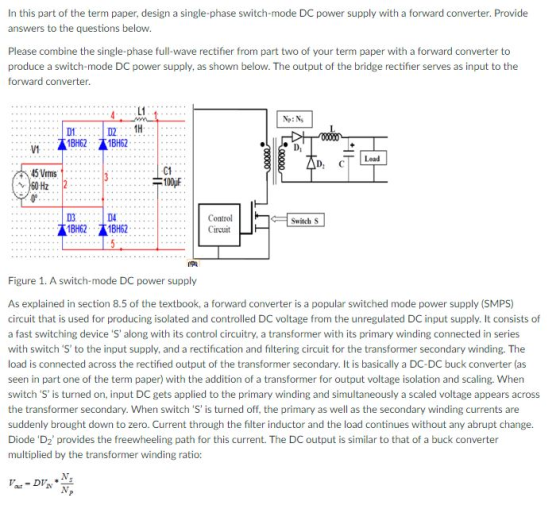

Assume all ideal components including the isolating transformr 2 and switch frequency is 16.7 kHz as in part one of the term paper. Design this switch-mode DC power supply by doing the following: . Determine the duty ratio D so that the DC output to the load is 12 v. Draw the waveform of the input AC voltage V1, bridge rectifier output (see part two of the term paper; this is also the input to the forward converter), voltage after diode D1, and voltage at the load (with all harmonics blocked). Explain why a transformer still works even with a DC input to the forward converter. Explain the function of diode D1. . Please include all necessary circuit diagrams or block diagrams in your paper. Please also draw the necessary waveforms together with your comments or discussion.
Homework Answers


Add Answer to:
In this part of the term paper, design a single-phase switch-mode DC power supply with a forward ...
You need to design a DC power supply that provides an average DC output voltage of...
 You need to design a DC power supply that provides an average DC output voltage of 5V to charge your cellphone. The maximum allowed ripple at the output is ±200 mV. Your cellphone can be modeled as a 1 50Ω load. You have to use a bridge rectifier with four diodes. Note: For calculations, consider constant voltage drop model of the diode with V0 = 0.7V. (a) The charger is designed to use in the US, i.e. transformer primary is...
Q4. Most electronic systems need a dc voltage to work properly. The AC-to-DC power supply system ...
 part g
Q4. Most electronic systems need a dc voltage to work properly. The AC-to-DC power supply system is including a transformer, a rectifier and a capacitor input filter. The AC input voltage is 110 Vrms at 60 Hz. (a) Draw the full wave bridge rectifier circuit with transformer which steps down voltage to safer and lower levels that are more suitable for use with diodes (b) Show how the capacitor input filter connects to the rectifier output in the...
part g
Q4. Most electronic systems need a dc voltage to work properly. The AC-to-DC power supply system is including a transformer, a rectifier and a capacitor input filter. The AC input voltage is 110 Vrms at 60 Hz. (a) Draw the full wave bridge rectifier circuit with transformer which steps down voltage to safer and lower levels that are more suitable for use with diodes (b) Show how the capacitor input filter connects to the rectifier output in the...
1. Power supply (ac to dc) design. [10 pts.] Design a full-wave bridge rectifier circuit to deliv...
 1. Power supply (ac to dc) design. [10 pts.] Design a full-wave bridge rectifier circuit to deliver 10 volts dc with less than 0.1 volt (peak to peak) ripple into a load drawing up to 10 mA. (a) Choose the appropriate ac input voltage from the transformer secondary assuming the usual voltage drops for silicon diodes. (b) Determine the correct capacitor value to ensure the specified ripple in your calculation (c) What fuse value should you select for the primary...
1. (35 points) Switch mode DC DC Converters. a. (15 points) Design a flyback DC/DC power converter to the following specifications. Assume ideal components Input Voltage Output Voltage Output Powe...
 1. (35 points) Switch mode DC DC Converters. a. (15 points) Design a flyback DC/DC power converter to the following specifications. Assume ideal components Input Voltage Output Voltage Output Power Switching frequency Maximum Current Ripple in the filter inductor Output ripple voltage: Continuous conduction 170 VDC 12 VDC 40 Watts 750 kHz 1.2 Amps Your answer should include a circuit diagram with each energy storage element labeled with its value. Label the transformer turns ratio.
1. (35 points) Switch mode...
1. (35 points) Switch mode DC DC Converters. a. (15 points) Design a flyback DC/DC power converter to the following specifications. Assume ideal components Input Voltage Output Voltage Output Power Switching frequency Maximum Current Ripple in the filter inductor Output ripple voltage: Continuous conduction 170 VDC 12 VDC 40 Watts 750 kHz 1.2 Amps Your answer should include a circuit diagram with each energy storage element labeled with its value. Label the transformer turns ratio.
1. (35 points) Switch mode...
Capacitor is connected to secondary (1) A fullwave bridge rectifier power supply is powered from the secondary of a transformer which has a peak secondary voltage of 22V. The primary of the transforme...
 Capacitor
is connected to secondary
(1) A fullwave bridge rectifier power supply is powered from the secondary of a transformer which has a peak secondary voltage of 22V. The primary of the transformer is connected to a 50Hz, 230Vus power supply. A 2700μF filter capacitor is used. A current of 1.5 Amp is drawn from the supply (i) Sketch a schematic diagram of the setup (ii) Calculate the mean dc output voltage (ii) Assume that each diode conducts for one-twelfth...
Capacitor
is connected to secondary
(1) A fullwave bridge rectifier power supply is powered from the secondary of a transformer which has a peak secondary voltage of 22V. The primary of the transformer is connected to a 50Hz, 230Vus power supply. A 2700μF filter capacitor is used. A current of 1.5 Amp is drawn from the supply (i) Sketch a schematic diagram of the setup (ii) Calculate the mean dc output voltage (ii) Assume that each diode conducts for one-twelfth...
% peak to peak ripple in Vdc- 20% determine minimum capacitance at output of boost converter 3. consider forward con...
 % peak to peak ripple in Vdc- 20%
determine minimum capacitance at output of boost converter
3. consider forward converter operating at 10khz with
the power in the table. the output voltage is 20v. the output
inductor is 90uh and turns ratio 1:1:1
I. operating mode?
ii. conduction loss in the forward converter switch if
switch resistance is 10milli ohm
Student #:- 2 125 Consider the following ACIDC folowed by a boost converner for active power factor correction, ana e...
% peak to peak ripple in Vdc- 20%
determine minimum capacitance at output of boost converter
3. consider forward converter operating at 10khz with
the power in the table. the output voltage is 20v. the output
inductor is 90uh and turns ratio 1:1:1
I. operating mode?
ii. conduction loss in the forward converter switch if
switch resistance is 10milli ohm
Student #:- 2 125 Consider the following ACIDC folowed by a boost converner for active power factor correction, ana e...
QUESTION ; If the turns ratio of the primary and tertiary windings of the forward transformer...
QUESTION ; If the turns ratio of the primary and tertiary windings of the forward transformer are in the ratio of 1:2, what is the maximum duty ratio at which the converter can be operated? Corresponding to this duty ratio, what should be the minimum ratio of secondary to primary turns if the input dc supply is 400 volts and the required output voltage is 15 volts? Neglect switch and diode conduction voltage drops.
Distortion current includes all the other harmonics than the fundamental true / false The main advantage...
Distortion current includes all the other harmonics than the fundamental true / false The main advantage of a synchronous buck converter is that the voltage drop across the low-side MOSFET can be higher than the voltage drop across the power diode of the nonsynchronous converter true / false A converter operates in the rectifier mode of operation when power is converted from AC to DC true / false The average value of the DC voltage in the output of a...
Buck Converter Question Q3. A Buck converter is used to produce a regulated 10V, 5A DC...
 Buck Converter Question
Q3. A Buck converter is used to produce a regulated 10V, 5A DC power supply from a variable DC source with an nominal input voltage of Vin = 20V±5V. The Buck converter switches at 250kHz, and operates entirely in the continuous conduction mode. The output filter capacitance is C1.0uF 3.a. Draw the circuit topology for the Buck converter. Ensure that your circuit includes the input DC source, the output load resistance, the switching devices (i.e. MOSFET and...
Buck Converter Question
Q3. A Buck converter is used to produce a regulated 10V, 5A DC power supply from a variable DC source with an nominal input voltage of Vin = 20V±5V. The Buck converter switches at 250kHz, and operates entirely in the continuous conduction mode. The output filter capacitance is C1.0uF 3.a. Draw the circuit topology for the Buck converter. Ensure that your circuit includes the input DC source, the output load resistance, the switching devices (i.e. MOSFET and...
It is required to use a FULL-wave rectifier to design a dc power supply that provides...
It is required to use a FULL-wave rectifier to design a dc power supply that provides an average dc output voltage of 15 V. A maximum ripple voltage of ±1 V is allowed on the output voltage. The output voltage will feed a load resistance of 250 Ω. Assume a sinusoidal input voltage with the frequency of 60 Hz. Do not include a Zener diode in your design. (Assume V_D0)* = 0.7 V). a) Draw the circuit diagram. b) Calculate...
 You need to design a DC power supply that provides an average DC output voltage of 5V to charge your cellphone. The maximum allowed ripple at the output is ±200 mV. Your cellphone can be modeled as a 1 50Ω load. You have to use a bridge rectifier with four diodes. Note: For calculations, consider constant voltage drop model of the diode with V0 = 0.7V. (a) The charger is designed to use in the US, i.e. transformer primary is...
 part g
Q4. Most electronic systems need a dc voltage to work properly. The AC-to-DC power supply system is including a transformer, a rectifier and a capacitor input filter. The AC input voltage is 110 Vrms at 60 Hz. (a) Draw the full wave bridge rectifier circuit with transformer which steps down voltage to safer and lower levels that are more suitable for use with diodes (b) Show how the capacitor input filter connects to the rectifier output in the...
part g
Q4. Most electronic systems need a dc voltage to work properly. The AC-to-DC power supply system is including a transformer, a rectifier and a capacitor input filter. The AC input voltage is 110 Vrms at 60 Hz. (a) Draw the full wave bridge rectifier circuit with transformer which steps down voltage to safer and lower levels that are more suitable for use with diodes (b) Show how the capacitor input filter connects to the rectifier output in the...
 1. Power supply (ac to dc) design. [10 pts.] Design a full-wave bridge rectifier circuit to deliver 10 volts dc with less than 0.1 volt (peak to peak) ripple into a load drawing up to 10 mA. (a) Choose the appropriate ac input voltage from the transformer secondary assuming the usual voltage drops for silicon diodes. (b) Determine the correct capacitor value to ensure the specified ripple in your calculation (c) What fuse value should you select for the primary...
 1. (35 points) Switch mode DC DC Converters. a. (15 points) Design a flyback DC/DC power converter to the following specifications. Assume ideal components Input Voltage Output Voltage Output Power Switching frequency Maximum Current Ripple in the filter inductor Output ripple voltage: Continuous conduction 170 VDC 12 VDC 40 Watts 750 kHz 1.2 Amps Your answer should include a circuit diagram with each energy storage element labeled with its value. Label the transformer turns ratio.
1. (35 points) Switch mode...
1. (35 points) Switch mode DC DC Converters. a. (15 points) Design a flyback DC/DC power converter to the following specifications. Assume ideal components Input Voltage Output Voltage Output Power Switching frequency Maximum Current Ripple in the filter inductor Output ripple voltage: Continuous conduction 170 VDC 12 VDC 40 Watts 750 kHz 1.2 Amps Your answer should include a circuit diagram with each energy storage element labeled with its value. Label the transformer turns ratio.
1. (35 points) Switch mode...
 Capacitor
is connected to secondary
(1) A fullwave bridge rectifier power supply is powered from the secondary of a transformer which has a peak secondary voltage of 22V. The primary of the transformer is connected to a 50Hz, 230Vus power supply. A 2700μF filter capacitor is used. A current of 1.5 Amp is drawn from the supply (i) Sketch a schematic diagram of the setup (ii) Calculate the mean dc output voltage (ii) Assume that each diode conducts for one-twelfth...
Capacitor
is connected to secondary
(1) A fullwave bridge rectifier power supply is powered from the secondary of a transformer which has a peak secondary voltage of 22V. The primary of the transformer is connected to a 50Hz, 230Vus power supply. A 2700μF filter capacitor is used. A current of 1.5 Amp is drawn from the supply (i) Sketch a schematic diagram of the setup (ii) Calculate the mean dc output voltage (ii) Assume that each diode conducts for one-twelfth...
 % peak to peak ripple in Vdc- 20%
determine minimum capacitance at output of boost converter
3. consider forward converter operating at 10khz with
the power in the table. the output voltage is 20v. the output
inductor is 90uh and turns ratio 1:1:1
I. operating mode?
ii. conduction loss in the forward converter switch if
switch resistance is 10milli ohm
Student #:- 2 125 Consider the following ACIDC folowed by a boost converner for active power factor correction, ana e...
% peak to peak ripple in Vdc- 20%
determine minimum capacitance at output of boost converter
3. consider forward converter operating at 10khz with
the power in the table. the output voltage is 20v. the output
inductor is 90uh and turns ratio 1:1:1
I. operating mode?
ii. conduction loss in the forward converter switch if
switch resistance is 10milli ohm
Student #:- 2 125 Consider the following ACIDC folowed by a boost converner for active power factor correction, ana e...
 Buck Converter Question
Q3. A Buck converter is used to produce a regulated 10V, 5A DC power supply from a variable DC source with an nominal input voltage of Vin = 20V±5V. The Buck converter switches at 250kHz, and operates entirely in the continuous conduction mode. The output filter capacitance is C1.0uF 3.a. Draw the circuit topology for the Buck converter. Ensure that your circuit includes the input DC source, the output load resistance, the switching devices (i.e. MOSFET and...
Buck Converter Question
Q3. A Buck converter is used to produce a regulated 10V, 5A DC power supply from a variable DC source with an nominal input voltage of Vin = 20V±5V. The Buck converter switches at 250kHz, and operates entirely in the continuous conduction mode. The output filter capacitance is C1.0uF 3.a. Draw the circuit topology for the Buck converter. Ensure that your circuit includes the input DC source, the output load resistance, the switching devices (i.e. MOSFET and...
Most questions answered within 3 hours.
-
Where is the error in this code sequence?
String s1 = "Hello";
String s2 = "ello";...
asked 11 months ago -
Financial data for Joel de Paris, Inc., for last year
follow:
Joel de Paris, Inc.
Balance...
asked 11 months ago -
Consider this reaction:
Al2(SO4)3 (aq)+ BaCl3
(aq) Al2Cl6 (aq)- +
3BaSO4(s) . What is the...
asked 11 months ago -
Suppose that Savneet is considering increasing her
recent random sample from 20 car rentals to 40...
asked 11 months ago -
Trucks arrive at an unloading terminal at an average rate of 120
per hour.
Trucks arrive...
asked 11 months ago -
Why are methanol and ethanol completely soluble in water while
octanol is not very little soluble....
asked 11 months ago -
A facilities manager at a university reads in a research report
that the mean amount of...
asked 11 months ago -
When the CuSO4 is rehydrated by adding water to the anhydrous
compound, is this an endothermic...
asked 11 months ago -
A ray of sunlight is passing from diamond into crown glass; the
angle of incidence is...
asked 11 months ago -
A block of mass 0.249 kg is placed on top of a light, vertical
spring of...
asked 11 months ago -
how do the kidneys compensate in the presences of acidosis
a) trigger hyperventilate
b) reserve acid...
asked 11 months ago -
Question 501 pts
The rental rate of capital to the firm increases. Which of the
following...
asked 11 months ago