1. Draw approximate discharge graphs.
2. Illustrate the circuit model that can be simulated in
PSPICE.
3. Compare steps 1 and 2 of the discussion.

Homework Answers
Ans 1)

Ans 2)

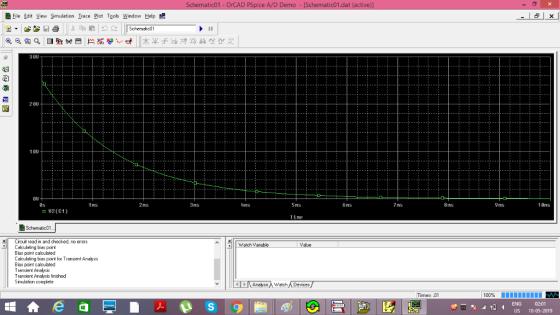
Ans 3) After comparison we get both the curves are approximately same.
Add Answer to:
1. Draw approximate discharge graphs. 2. Illustrate the circuit model that can be simulated in PSPICE. 3. Compare steps 1 and 2 of the discussion. 1.0 kΩ 1.0 kΩ
Ignore PSpice Simulation Design the MOSFET current mirror shown in Figure 2 to replicate a 1...
 Ignore PSpice Simulation
Design the MOSFET current mirror shown in Figure 2 to replicate a 1 mA reference current at the drain ofM2. Assume Vtn-1.2 V, L-100 μm, W-100 μm, kh-0.093 A/V2, and V,-100 1. Determine Ri such that IREF 1 mA is the current, Ipi, flowing into the drain of Mi. 2. Calculate lolREF, where lo = 1D2. 3. Simulate the circuit in Figure 2 in PSpice. Use the SEDRA LIB library for the MOSFET transistors and enter the...
Ignore PSpice Simulation
Design the MOSFET current mirror shown in Figure 2 to replicate a 1 mA reference current at the drain ofM2. Assume Vtn-1.2 V, L-100 μm, W-100 μm, kh-0.093 A/V2, and V,-100 1. Determine Ri such that IREF 1 mA is the current, Ipi, flowing into the drain of Mi. 2. Calculate lolREF, where lo = 1D2. 3. Simulate the circuit in Figure 2 in PSpice. Use the SEDRA LIB library for the MOSFET transistors and enter the...
how to draw this circuit in pspice PRE-LAB Resistors 150kQ, 180k2, 220k2, 270k2, 330k2, 39k02, 470k2, 560kQ Part A. I...
 how to draw this circuit in pspice
PRE-LAB Resistors 150kQ, 180k2, 220k2, 270k2, 330k2, 39k02, 470k2, 560kQ Part A. Inverting Amplifier. Deliverables - PSpice schematie and graphs 1. Draw the circuit for a standard inverting amplifier (see text). You can leave the resistors variables for now: Ai 2. Choose the resistor values from components available for this lab in the list above to give a gain between 5 and 10. Use values of 5.6 kΩ or greater. Record the resistor...
how to draw this circuit in pspice
PRE-LAB Resistors 150kQ, 180k2, 220k2, 270k2, 330k2, 39k02, 470k2, 560kQ Part A. Inverting Amplifier. Deliverables - PSpice schematie and graphs 1. Draw the circuit for a standard inverting amplifier (see text). You can leave the resistors variables for now: Ai 2. Choose the resistor values from components available for this lab in the list above to give a gain between 5 and 10. Use values of 5.6 kΩ or greater. Record the resistor...
Only answer part C. (b) Calculate the current 1 if Rf = 10 MQ, R-90 kQ, R2-10 kΩ and V-0.1 V (c) Model the circuit of F...
 Only answer part C.
(b) Calculate the current 1 if Rf = 10 MQ, R-90 kQ, R2-10 kΩ and V-0.1 V (c) Model the circuit of FIGURE 2 using PSPICE [using an ideal op- I to confirm the calculation made 2 FIG. 2
(b) Calculate the current 1 if Rf = 10 MQ, R-90 kQ, R2-10 kΩ and V-0.1 V (c) Model the circuit of FIGURE 2 using PSPICE [using an ideal op- I to confirm the calculation made 2...
Only answer part C.
(b) Calculate the current 1 if Rf = 10 MQ, R-90 kQ, R2-10 kΩ and V-0.1 V (c) Model the circuit of FIGURE 2 using PSPICE [using an ideal op- I to confirm the calculation made 2 FIG. 2
(b) Calculate the current 1 if Rf = 10 MQ, R-90 kQ, R2-10 kΩ and V-0.1 V (c) Model the circuit of FIGURE 2 using PSPICE [using an ideal op- I to confirm the calculation made 2...
done on pspice thank you Part IV: Diode Rectifiers Procedure: 1. Build the circuit model for...
 done on pspice thank you
Part IV: Diode Rectifiers Procedure: 1. Build the circuit model for full-wave diode rectifier in PSpice as shown in Fig. 4. The value of the load resistor is 10 k22. The input AC voltage source (VSIN in PSpice) is configured at 100 Hz and 20 V (peak-to- peak) in sinusoidal waveform. O 10K V.(t) V(A) A Figure 4. Circuit configuration for full-wave diode rectifier 2. Run the simulation and save the input and output voltage...
done on pspice thank you
Part IV: Diode Rectifiers Procedure: 1. Build the circuit model for full-wave diode rectifier in PSpice as shown in Fig. 4. The value of the load resistor is 10 k22. The input AC voltage source (VSIN in PSpice) is configured at 100 Hz and 20 V (peak-to- peak) in sinusoidal waveform. O 10K V.(t) V(A) A Figure 4. Circuit configuration for full-wave diode rectifier 2. Run the simulation and save the input and output voltage...
Design the BJT current mirror shown in Figure 1 to replicate a 1 mA reference current at the coll...
 Ignore PSpice Simulation
Design the BJT current mirror shown in Figure 1 to replicate a 1 mA reference current at the collector of 02. Assume a scale current of 6.7 fA, V 74 V, and B-200. 1. Determine Ri such that IREF- 1 mA is the current, Ic, flowing into the collector of Qi 2. Calculate Io/IREF, where Io- Ic2. 3. Simulate the circuit in Figure 1 in PSpice. Use the SEDRA_LIB library for the Q2N3904 and enter the appropriate...
Ignore PSpice Simulation
Design the BJT current mirror shown in Figure 1 to replicate a 1 mA reference current at the collector of 02. Assume a scale current of 6.7 fA, V 74 V, and B-200. 1. Determine Ri such that IREF- 1 mA is the current, Ic, flowing into the collector of Qi 2. Calculate Io/IREF, where Io- Ic2. 3. Simulate the circuit in Figure 1 in PSpice. Use the SEDRA_LIB library for the Q2N3904 and enter the appropriate...
SL= -2 + 2w DL= 14 - 2w Draw graphs to illustrate solutions. 3. Suppose that...
SL= -2 + 2w DL= 14 - 2w Draw graphs to illustrate solutions. 3. Suppose that this labor market becomes monopsonistic and that the marginal cost of labor can be described by the following relation: MWC= 1 + L 3. Suppose a minimum wage of 6$ is imposed in this market. What will happen to the amount of labor hired by the firm? 4. What is the highest minimum wage that could be imposed on this market without a loss...
SL= -2 + 2w DL= 14 - 2w Draw graphs to illustrate solutions. 1. Solve for...
SL= -2 + 2w DL= 14 - 2w Draw graphs to illustrate solutions. 1. Solve for the equilibrium wage rate and level of employment. 2. Assume that a minimum wage of 6 is imposed in this market. 5. What is the loss of GDP as a result of the minimum wage, assuming workers ARE reemployed elsewhere? 6. What is the loss of GDP as a result of the minimum wage, assuming workers ARE NOT reemployed elsewhere?
Part I: Inverting Amplifier Procedure: 1. Build the circuit model for inverting amplifier in PSpice with...
 Part I: Inverting Amplifier Procedure: 1. Build the circuit model for inverting amplifier in PSpice with the following parameters: Ri = 5 k 2, R2 = 20 ks2, V+ = 10 V, V-=-10 V. 2. Hand calculates the theoretical closed loop gain Vout/Vin of the circuit model. 3. Generate a triangular waveform for Vin with the amplitude of 1 V and the period of 1 ms. 4. Run simulation. a. Set circuit model parameters. i.e., for voltage source: click VPWL...
Data Analysis (30 points) This part is for data analysis. You can insert graphs and a...
Data Analysis (30 points) This part is for data analysis. You can insert graphs and a sample of your calculation. A B and C are the fitting parameters, and the time constant can be calculated from the constant "C" as τ=1/C Table 2 Charging Discharging R A B C τ (s) A B C τ (s) 22 kΩ 0.862 -3.2 2.66 0.376 -3.17 -0.019 0.043 23.256 47 kΩ 4.13 -3.2 1.66 0.503 -3.12 -0.018 0.044 22.989 100 kΩ 2.9 -3.07...
This discussion question should be addressed in these three steps: 1. Discuss how a manager can...
This discussion question should be addressed in these three steps: 1. Discuss how a manager can control employees to make necessary changes in an HCO. 2. How do you feel about using intuition rather than rational thinking to make decisions? 3. Compare and contrast radical change and incremental change. 4. Discuss how nonverbal communication is important for managers
 Ignore PSpice Simulation
Design the MOSFET current mirror shown in Figure 2 to replicate a 1 mA reference current at the drain ofM2. Assume Vtn-1.2 V, L-100 μm, W-100 μm, kh-0.093 A/V2, and V,-100 1. Determine Ri such that IREF 1 mA is the current, Ipi, flowing into the drain of Mi. 2. Calculate lolREF, where lo = 1D2. 3. Simulate the circuit in Figure 2 in PSpice. Use the SEDRA LIB library for the MOSFET transistors and enter the...
Ignore PSpice Simulation
Design the MOSFET current mirror shown in Figure 2 to replicate a 1 mA reference current at the drain ofM2. Assume Vtn-1.2 V, L-100 μm, W-100 μm, kh-0.093 A/V2, and V,-100 1. Determine Ri such that IREF 1 mA is the current, Ipi, flowing into the drain of Mi. 2. Calculate lolREF, where lo = 1D2. 3. Simulate the circuit in Figure 2 in PSpice. Use the SEDRA LIB library for the MOSFET transistors and enter the...
 how to draw this circuit in pspice
PRE-LAB Resistors 150kQ, 180k2, 220k2, 270k2, 330k2, 39k02, 470k2, 560kQ Part A. Inverting Amplifier. Deliverables - PSpice schematie and graphs 1. Draw the circuit for a standard inverting amplifier (see text). You can leave the resistors variables for now: Ai 2. Choose the resistor values from components available for this lab in the list above to give a gain between 5 and 10. Use values of 5.6 kΩ or greater. Record the resistor...
how to draw this circuit in pspice
PRE-LAB Resistors 150kQ, 180k2, 220k2, 270k2, 330k2, 39k02, 470k2, 560kQ Part A. Inverting Amplifier. Deliverables - PSpice schematie and graphs 1. Draw the circuit for a standard inverting amplifier (see text). You can leave the resistors variables for now: Ai 2. Choose the resistor values from components available for this lab in the list above to give a gain between 5 and 10. Use values of 5.6 kΩ or greater. Record the resistor...
 Only answer part C.
(b) Calculate the current 1 if Rf = 10 MQ, R-90 kQ, R2-10 kΩ and V-0.1 V (c) Model the circuit of FIGURE 2 using PSPICE [using an ideal op- I to confirm the calculation made 2 FIG. 2
(b) Calculate the current 1 if Rf = 10 MQ, R-90 kQ, R2-10 kΩ and V-0.1 V (c) Model the circuit of FIGURE 2 using PSPICE [using an ideal op- I to confirm the calculation made 2...
Only answer part C.
(b) Calculate the current 1 if Rf = 10 MQ, R-90 kQ, R2-10 kΩ and V-0.1 V (c) Model the circuit of FIGURE 2 using PSPICE [using an ideal op- I to confirm the calculation made 2 FIG. 2
(b) Calculate the current 1 if Rf = 10 MQ, R-90 kQ, R2-10 kΩ and V-0.1 V (c) Model the circuit of FIGURE 2 using PSPICE [using an ideal op- I to confirm the calculation made 2...
 done on pspice thank you
Part IV: Diode Rectifiers Procedure: 1. Build the circuit model for full-wave diode rectifier in PSpice as shown in Fig. 4. The value of the load resistor is 10 k22. The input AC voltage source (VSIN in PSpice) is configured at 100 Hz and 20 V (peak-to- peak) in sinusoidal waveform. O 10K V.(t) V(A) A Figure 4. Circuit configuration for full-wave diode rectifier 2. Run the simulation and save the input and output voltage...
done on pspice thank you
Part IV: Diode Rectifiers Procedure: 1. Build the circuit model for full-wave diode rectifier in PSpice as shown in Fig. 4. The value of the load resistor is 10 k22. The input AC voltage source (VSIN in PSpice) is configured at 100 Hz and 20 V (peak-to- peak) in sinusoidal waveform. O 10K V.(t) V(A) A Figure 4. Circuit configuration for full-wave diode rectifier 2. Run the simulation and save the input and output voltage...
 Ignore PSpice Simulation
Design the BJT current mirror shown in Figure 1 to replicate a 1 mA reference current at the collector of 02. Assume a scale current of 6.7 fA, V 74 V, and B-200. 1. Determine Ri such that IREF- 1 mA is the current, Ic, flowing into the collector of Qi 2. Calculate Io/IREF, where Io- Ic2. 3. Simulate the circuit in Figure 1 in PSpice. Use the SEDRA_LIB library for the Q2N3904 and enter the appropriate...
Ignore PSpice Simulation
Design the BJT current mirror shown in Figure 1 to replicate a 1 mA reference current at the collector of 02. Assume a scale current of 6.7 fA, V 74 V, and B-200. 1. Determine Ri such that IREF- 1 mA is the current, Ic, flowing into the collector of Qi 2. Calculate Io/IREF, where Io- Ic2. 3. Simulate the circuit in Figure 1 in PSpice. Use the SEDRA_LIB library for the Q2N3904 and enter the appropriate...
 Part I: Inverting Amplifier Procedure: 1. Build the circuit model for inverting amplifier in PSpice with the following parameters: Ri = 5 k 2, R2 = 20 ks2, V+ = 10 V, V-=-10 V. 2. Hand calculates the theoretical closed loop gain Vout/Vin of the circuit model. 3. Generate a triangular waveform for Vin with the amplitude of 1 V and the period of 1 ms. 4. Run simulation. a. Set circuit model parameters. i.e., for voltage source: click VPWL...
Most questions answered within 3 hours.
-
Where is the error in this code sequence?
String s1 = "Hello";
String s2 = "ello";...
asked 11 months ago -
Financial data for Joel de Paris, Inc., for last year
follow:
Joel de Paris, Inc.
Balance...
asked 11 months ago -
Consider this reaction:
Al2(SO4)3 (aq)+ BaCl3
(aq) Al2Cl6 (aq)- +
3BaSO4(s) . What is the...
asked 11 months ago -
Suppose that Savneet is considering increasing her
recent random sample from 20 car rentals to 40...
asked 11 months ago -
Trucks arrive at an unloading terminal at an average rate of 120
per hour.
Trucks arrive...
asked 11 months ago -
Why are methanol and ethanol completely soluble in water while
octanol is not very little soluble....
asked 11 months ago -
A facilities manager at a university reads in a research report
that the mean amount of...
asked 11 months ago -
When the CuSO4 is rehydrated by adding water to the anhydrous
compound, is this an endothermic...
asked 11 months ago -
A ray of sunlight is passing from diamond into crown glass; the
angle of incidence is...
asked 11 months ago -
A block of mass 0.249 kg is placed on top of a light, vertical
spring of...
asked 11 months ago -
how do the kidneys compensate in the presences of acidosis
a) trigger hyperventilate
b) reserve acid...
asked 11 months ago -
Question 501 pts
The rental rate of capital to the firm increases. Which of the
following...
asked 11 months ago