
Homework Answers

Add Answer to:
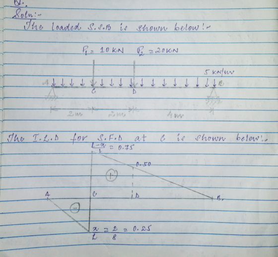
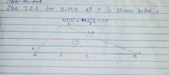
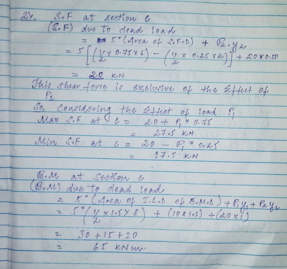
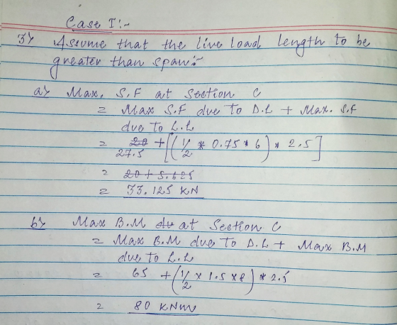
Question 2: A simply supported beam under loading as shown in Figure 1: 1. Draw the influence lines of the bending moment and shear force at point C (L/4) Using the influence lines to determine t...
Shear force and bending moments of the beam. For the simply supported beam subjected to the...
 Shear force and bending moments of the beam.
For the simply supported beam subjected to the loading shown in Figure P7.8 derive equations for the shear force V and the bending moment M for any location in the beam. (Place the origin at point A.) plot the shear-force and bending-moment diagrams for the beam, using the derived functions. report the maximum positive bending moment, the maximum negative bending moment, and their respective locations.
Shear force and bending moments of the beam.
For the simply supported beam subjected to the loading shown in Figure P7.8 derive equations for the shear force V and the bending moment M for any location in the beam. (Place the origin at point A.) plot the shear-force and bending-moment diagrams for the beam, using the derived functions. report the maximum positive bending moment, the maximum negative bending moment, and their respective locations.
QUESTION 1 [15] For the simply supported beam subjected to the loading shown in the figure,...
 QUESTION 1 [15] For the simply supported beam subjected to the loading shown in the figure, a) Derive equations for the shear force V and the bending moment M for any location in the beam. (Place the origin at point A.) b) Report the maximum positive bending moment, the maximum negative bending moment, and their respective locations. 36 KN 180 KN-m X B C D 4 m 5 m 3 m Figure 1
4. For the beam and loading shown, draw the shear force and bending moment diagrams and...
 4. For the beam and loading shown, draw the shear force and bending moment diagrams and determine the maximum bending and shear force and their locations. 20 KN 40 KN B D 250 mm |--2.5 m- 3m-4-2 m 80 mm 5. For the beam and loading shown, draw the shear force and bending moment diagrams and determine the maximum bending and shear force and their locations. 50 KN
Draw the shear force and bending-moment diagrams for the simply supported beam shown. Label each diagram...
 Draw the shear force and bending-moment diagrams for the simply
supported beam shown. Label each diagram with the corresponding
values
1. Draw the shear force and bending-moment diagrams for the simply supported beam shown. Label each diagram with the corresponding values. 3 Pe= 30 KN 4 m - m 3 m - C -40 kN - m
Draw the shear force and bending-moment diagrams for the simply
supported beam shown. Label each diagram with the corresponding
values
1. Draw the shear force and bending-moment diagrams for the simply supported beam shown. Label each diagram with the corresponding values. 3 Pe= 30 KN 4 m - m 3 m - C -40 kN - m
1. For the simply supported beam subjected to the loading shown, Derive equations for the shear...
 1. For the simply supported beam subjected to the loading shown, Derive equations for the shear force V and the bending moment M for any location in the beam. (Place the origin at point A.) a. b. Plot the shear-force and bending-moment diagrams for the beam using the derived functions c. Report the maximum bending moment and its location. 42 kips 6 kips/ft 10 ft 20 ft
a simply supported beam abcd with arectangular cross sectioncarries the loading shown in figure. the...
 a simply supported beam abcd with arectangular cross section
carries the loading shown in figure. the uniform beam has a mass of
33 kg per meter (m kg/m) and a cross section as shown in the
figure. you may take 10 m/s^2 as acceleration.Question A2 A simply supported beam ABCD with a rectangular cross-section carries the loading shown in Figure QA2. The uniform beam has a mass of m kg per meter of length (m kg/m) and a cross-section as shown...
a simply supported beam abcd with arectangular cross section
carries the loading shown in figure. the uniform beam has a mass of
33 kg per meter (m kg/m) and a cross section as shown in the
figure. you may take 10 m/s^2 as acceleration.Question A2 A simply supported beam ABCD with a rectangular cross-section carries the loading shown in Figure QA2. The uniform beam has a mass of m kg per meter of length (m kg/m) and a cross-section as shown...
Draw the shear and bending-moment diagrams for the beam and loading shown.
 Required information Consider the given beam and loading. Draw the shear and bending-moment diagrams for the beam and loading shown.Determine the maximum absolute values of the shear and bending moment. (Round the final answer to one decimal place.) The maximum absolute shear force is _______ KN. The maximum absolute bending moment is _______ kN.m.
For the beam and loading shown, draw the shear and bending moment diagrams, and determine the...
 For the beam and loading shown, draw the shear and bending moment diagrams, and determine the magnitude and location of the maximum shear and bending moment. 2 kN/m AC D 6 NT 3kN/m lm-- 1.2 m 0.6 m
Question 5 10 points Save Answ Draw the shear-force and bending-moment diagrams for the simply supported...
 Question 5 10 points Save Answ Draw the shear-force and bending-moment diagrams for the simply supported beam shown. Determine the bending moment 3.6 m to the right of point A if W = 9.1 kN/m, T = 17.34 kNm, m = 11.9 m, and n = 3.7 m. W T С о В n Question 6 10 points Save Answer Draw the shear-force and bending-moment diagrams for the simply supported beam shown. Determine the shear force 3.3 m to the...
1. Draw influence lines for shear and moment at 15, 25, and 30 feet from the left support for a simply supported be...
 1. Draw influence lines for shear and moment at 15, 25, and 30 feet from the left support for a simply supported beam with a span of 60 feet. Show values of maxima. 2. Using the influence lines in part 1, determine the shear and moment at 15, 25, and 30 feet for a uniformly distributed load of 50 k/ft applied over the length of the beam required to produce the maximum shear and moment at each point. 3. Using...
 Shear force and bending moments of the beam.
For the simply supported beam subjected to the loading shown in Figure P7.8 derive equations for the shear force V and the bending moment M for any location in the beam. (Place the origin at point A.) plot the shear-force and bending-moment diagrams for the beam, using the derived functions. report the maximum positive bending moment, the maximum negative bending moment, and their respective locations.
Shear force and bending moments of the beam.
For the simply supported beam subjected to the loading shown in Figure P7.8 derive equations for the shear force V and the bending moment M for any location in the beam. (Place the origin at point A.) plot the shear-force and bending-moment diagrams for the beam, using the derived functions. report the maximum positive bending moment, the maximum negative bending moment, and their respective locations.
 QUESTION 1 [15] For the simply supported beam subjected to the loading shown in the figure, a) Derive equations for the shear force V and the bending moment M for any location in the beam. (Place the origin at point A.) b) Report the maximum positive bending moment, the maximum negative bending moment, and their respective locations. 36 KN 180 KN-m X B C D 4 m 5 m 3 m Figure 1
 4. For the beam and loading shown, draw the shear force and bending moment diagrams and determine the maximum bending and shear force and their locations. 20 KN 40 KN B D 250 mm |--2.5 m- 3m-4-2 m 80 mm 5. For the beam and loading shown, draw the shear force and bending moment diagrams and determine the maximum bending and shear force and their locations. 50 KN
 Draw the shear force and bending-moment diagrams for the simply
supported beam shown. Label each diagram with the corresponding
values
1. Draw the shear force and bending-moment diagrams for the simply supported beam shown. Label each diagram with the corresponding values. 3 Pe= 30 KN 4 m - m 3 m - C -40 kN - m
Draw the shear force and bending-moment diagrams for the simply
supported beam shown. Label each diagram with the corresponding
values
1. Draw the shear force and bending-moment diagrams for the simply supported beam shown. Label each diagram with the corresponding values. 3 Pe= 30 KN 4 m - m 3 m - C -40 kN - m
 1. For the simply supported beam subjected to the loading shown, Derive equations for the shear force V and the bending moment M for any location in the beam. (Place the origin at point A.) a. b. Plot the shear-force and bending-moment diagrams for the beam using the derived functions c. Report the maximum bending moment and its location. 42 kips 6 kips/ft 10 ft 20 ft
 a simply supported beam abcd with arectangular cross section
carries the loading shown in figure. the uniform beam has a mass of
33 kg per meter (m kg/m) and a cross section as shown in the
figure. you may take 10 m/s^2 as acceleration.Question A2 A simply supported beam ABCD with a rectangular cross-section carries the loading shown in Figure QA2. The uniform beam has a mass of m kg per meter of length (m kg/m) and a cross-section as shown...
a simply supported beam abcd with arectangular cross section
carries the loading shown in figure. the uniform beam has a mass of
33 kg per meter (m kg/m) and a cross section as shown in the
figure. you may take 10 m/s^2 as acceleration.Question A2 A simply supported beam ABCD with a rectangular cross-section carries the loading shown in Figure QA2. The uniform beam has a mass of m kg per meter of length (m kg/m) and a cross-section as shown...
 For the beam and loading shown, draw the shear and bending moment diagrams, and determine the magnitude and location of the maximum shear and bending moment. 2 kN/m AC D 6 NT 3kN/m lm-- 1.2 m 0.6 m
 Question 5 10 points Save Answ Draw the shear-force and bending-moment diagrams for the simply supported beam shown. Determine the bending moment 3.6 m to the right of point A if W = 9.1 kN/m, T = 17.34 kNm, m = 11.9 m, and n = 3.7 m. W T С о В n Question 6 10 points Save Answer Draw the shear-force and bending-moment diagrams for the simply supported beam shown. Determine the shear force 3.3 m to the...
 1. Draw influence lines for shear and moment at 15, 25, and 30 feet from the left support for a simply supported beam with a span of 60 feet. Show values of maxima. 2. Using the influence lines in part 1, determine the shear and moment at 15, 25, and 30 feet for a uniformly distributed load of 50 k/ft applied over the length of the beam required to produce the maximum shear and moment at each point. 3. Using...
Most questions answered within 3 hours.
-
Where is the error in this code sequence?
String s1 = "Hello";
String s2 = "ello";...
asked 11 months ago -
Financial data for Joel de Paris, Inc., for last year
follow:
Joel de Paris, Inc.
Balance...
asked 11 months ago -
Consider this reaction:
Al2(SO4)3 (aq)+ BaCl3
(aq) Al2Cl6 (aq)- +
3BaSO4(s) . What is the...
asked 11 months ago -
Suppose that Savneet is considering increasing her
recent random sample from 20 car rentals to 40...
asked 11 months ago -
Trucks arrive at an unloading terminal at an average rate of 120
per hour.
Trucks arrive...
asked 11 months ago -
Why are methanol and ethanol completely soluble in water while
octanol is not very little soluble....
asked 11 months ago -
A facilities manager at a university reads in a research report
that the mean amount of...
asked 11 months ago -
When the CuSO4 is rehydrated by adding water to the anhydrous
compound, is this an endothermic...
asked 11 months ago -
A ray of sunlight is passing from diamond into crown glass; the
angle of incidence is...
asked 11 months ago -
A block of mass 0.249 kg is placed on top of a light, vertical
spring of...
asked 11 months ago -
how do the kidneys compensate in the presences of acidosis
a) trigger hyperventilate
b) reserve acid...
asked 11 months ago -
Question 501 pts
The rental rate of capital to the firm increases. Which of the
following...
asked 11 months ago