
please fill in the rest thanks

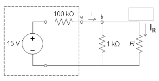
A. What is the range of possible values of ? (HINT: What are the extremes for the possible values for ORK) I. Calculate the required value of R such that IR-50 μΑ of current. (SHOW YOUR W B. One approach: Kirchoff's Current Law (KCL) I, - 12tIe 15V R1 Vail-VheadIR Ri RiR) CR.tl)V R= ing r49 一2. Using the resistor substitution box, place the value of R determined in Part II.B. 1 in the circuit. Measure the current through R by placing an ammeter in series with it. 3, Calculate the percent difference between B.2 and the desired 50 μA current. %Diff-
1. Measure i by replacing the short circuit between nodes a and b with the ammeter. C. 2. Using the measured value of i, and all nominal resistor values, calculate the current through the 1 kΩ resistor. (SHOW YOUR WORK) lk 3. Use KCL (1 resistor, ik in + R, with İR from B.2, and i from C. 1) to determine the current through the l Ω lk 4. Calculate the percent difference between the results of C.2 and C.3. %Diff
Homework Answers

Add Answer to:
please fill in the rest thanks 15 V A. What is the range of possible values of ? (HINT: What are the extremes for the possible values for ORK) I. Calculate the required value of R such that IR-50 μ...
Answer 4 & 5 please! thank you! R values = Resistor value, R1 = 990 Ohms...
 Answer 4 & 5 please! thank
you!
R values =
Resistor value, R1 = 990 Ohms
Resistor value, R2 = 2050 Ohms
4. Connect the 2nd resistor in parallel with the 1st
resistor and connect that combination to the battery.
Measure
the following:
The
current passing through the R1, I1 = ___0.0058____ A
The
current passing through the R2, I2 = ___0.0031____ A
The
current supplied by the battery, I = ___0.0092____ A
Calculate I1 + I2 =...
Answer 4 & 5 please! thank
you!
R values =
Resistor value, R1 = 990 Ohms
Resistor value, R2 = 2050 Ohms
4. Connect the 2nd resistor in parallel with the 1st
resistor and connect that combination to the battery.
Measure
the following:
The
current passing through the R1, I1 = ___0.0058____ A
The
current passing through the R2, I2 = ___0.0031____ A
The
current supplied by the battery, I = ___0.0092____ A
Calculate I1 + I2 =...
With the given information, what are the following values? Also, sorry for the picture quality. it...
 With the given information, what are the following
values?
Also, sorry for the picture quality. it was the best I could
do.
The voltage is 0.528 V(in volts) and the current is in
amperes. However, I think it needs to be converting to mA. So, I
believe the current is 0.1483 mA, 0.0925 mA, 0.00498 mA.
Parallel Circuit Voltage V Total current A Observed total Ω Theoretical Rotal 12 Do the observed results agree reasonably with the experimental value? 1....
With the given information, what are the following
values?
Also, sorry for the picture quality. it was the best I could
do.
The voltage is 0.528 V(in volts) and the current is in
amperes. However, I think it needs to be converting to mA. So, I
believe the current is 0.1483 mA, 0.0925 mA, 0.00498 mA.
Parallel Circuit Voltage V Total current A Observed total Ω Theoretical Rotal 12 Do the observed results agree reasonably with the experimental value? 1....
Please help me answer this 3-part question based on the information that follows, showing work when...
 Please help me answer this 3-part question based on the
information that follows, showing work when helpful:
a. What is the effective resistance of the resistors you
used for number 3?
b. Which of your measurements had the smallest relative
uncertainty?
c. Batteries have an internal resistance, which we have
not considered in the lab. How would the internal resistance of
your battery affected your calculations for part a?
R1=10 KiloOhms, R2=2.2 KiloOhms, R3=1 KiloOhm, E1 and E2 each
equal...
Please help me answer this 3-part question based on the
information that follows, showing work when helpful:
a. What is the effective resistance of the resistors you
used for number 3?
b. Which of your measurements had the smallest relative
uncertainty?
c. Batteries have an internal resistance, which we have
not considered in the lab. How would the internal resistance of
your battery affected your calculations for part a?
R1=10 KiloOhms, R2=2.2 KiloOhms, R3=1 KiloOhm, E1 and E2 each
equal...
i dont undersrand how to calculate the values from measured data? 2. Turn on the DC...
 i dont undersrand how to calculate the values from measured
data?
2. Turn on the DC power supply, measure its output voltage with DMM2 and record it as measured data Vs in Table 6. 3. Use DMM2 to measure the voltages V, V2.V. Va across R R. RR respectively. Use DMMI to measure the current Is (notice: Is=1= 12 + 1,-1). Record the measured values of I, and V., V2, V3. V4 in Table 6. 4. Turn off the DC...
i dont undersrand how to calculate the values from measured
data?
2. Turn on the DC power supply, measure its output voltage with DMM2 and record it as measured data Vs in Table 6. 3. Use DMM2 to measure the voltages V, V2.V. Va across R R. RR respectively. Use DMMI to measure the current Is (notice: Is=1= 12 + 1,-1). Record the measured values of I, and V., V2, V3. V4 in Table 6. 4. Turn off the DC...
I NEED HELP WITH QUESTION #5 PLEASE AND CAN SOME FILL OUT THE FIRST ROW OF...
 I NEED HELP WITH QUESTION #5 PLEASE AND CAN SOME FILL OUT THE
FIRST ROW OF MY TABLE FOR 10Hz. I DONT KNOW HOW TO DO IT SO IF SOME
CAN FILL OUT THE FIRST TABLE AND SHOW ME HOW, THEN I CAN FINISH THE
REST. THANK YOU.
Reset Run / STOP 2uF Simulation Speed Current Speed 0 Power Brightness Current Circuit: 10Hz 1k New X S -15.933 V 100.165 ms 167.681 V capacitor, 2 UF 21.071 V resistor, 1...
I NEED HELP WITH QUESTION #5 PLEASE AND CAN SOME FILL OUT THE
FIRST ROW OF MY TABLE FOR 10Hz. I DONT KNOW HOW TO DO IT SO IF SOME
CAN FILL OUT THE FIRST TABLE AND SHOW ME HOW, THEN I CAN FINISH THE
REST. THANK YOU.
Reset Run / STOP 2uF Simulation Speed Current Speed 0 Power Brightness Current Circuit: 10Hz 1k New X S -15.933 V 100.165 ms 167.681 V capacitor, 2 UF 21.071 V resistor, 1...
2- Set the two independent power sources to Vsi 6V and Veo" 10 V and measure...
 2- Set the two independent power sources to Vsi 6V and Veo" 10 V and measure their actual values using the DMM. Actual Values of power sources: 4.47 VS15.99 Vs- 3- Using the breadboard construct the circuit shown in Figure 4,1 (repeated below for convenience). Use the resistors measured in Step 1 (above) and the power sources Vsi- 6 V, and Vs2 -10 V. IR3 IRI RS. R5 R1 R3 Va V4 V2 V1 ww ww It 12 R4 R23...
CAN SOMEONE FILL OUT THIS TABLE PLEASE?? I HAVE TRIED MULTIPLE TIME AND I AM NOT...
 CAN SOMEONE FILL OUT THIS TABLE PLEASE?? I HAVE TRIED MULTIPLE
TIME AND I AM NOT GETTING ANYTHING RIGHT.
THANK YOU :))))
2uF 10HZ 1k PREPARATION In an AC circuit capacitors and inductors have an effective resistance that restricts the flow of current, this is known as impedance. An equivalent to Ohm's law can be written where resistance R is replaced by the impedance Z: V = 12 (9-4) where V and I are either the root mean squares or...
CAN SOMEONE FILL OUT THIS TABLE PLEASE?? I HAVE TRIED MULTIPLE
TIME AND I AM NOT GETTING ANYTHING RIGHT.
THANK YOU :))))
2uF 10HZ 1k PREPARATION In an AC circuit capacitors and inductors have an effective resistance that restricts the flow of current, this is known as impedance. An equivalent to Ohm's law can be written where resistance R is replaced by the impedance Z: V = 12 (9-4) where V and I are either the root mean squares or...
I need help with numbers 4,6,7,8,9 please? 12 VDC 1.0 k ohms 10k ohms C3 1.0 uF C1 1.0 UF , R Load Baca 1 80 10k ohns 300 mVp-p 1.0 kHz 100 ohms .7k ohms C2 47uF 330 ohms 4. Calculate the following pa...
 I need help with numbers 4,6,7,8,9 please?
12 VDC 1.0 k ohms 10k ohms C3 1.0 uF C1 1.0 UF , R Load Baca 1 80 10k ohns 300 mVp-p 1.0 kHz 100 ohms .7k ohms C2 47uF 330 ohms 4. Calculate the following parameters assuming capacitor C2 has been removed from the circuit with the 1.0k2 resistor as the load. RIN BASE Av Vour 5. Construct the circuit shown on the previous page. Before connecting the AC supply, measure...
I need help with numbers 4,6,7,8,9 please?
12 VDC 1.0 k ohms 10k ohms C3 1.0 uF C1 1.0 UF , R Load Baca 1 80 10k ohns 300 mVp-p 1.0 kHz 100 ohms .7k ohms C2 47uF 330 ohms 4. Calculate the following parameters assuming capacitor C2 has been removed from the circuit with the 1.0k2 resistor as the load. RIN BASE Av Vour 5. Construct the circuit shown on the previous page. Before connecting the AC supply, measure...
please help with problems 7 and 8, I am extremely confused! Part 2: Kirchhoff's Rules For...
 please help with problems 7 and 8, I am extremely
confused!
Part 2: Kirchhoff's Rules For the circuit shown below, the directions of the currents through the circuit elements has been chosen arbitrarily. Using Kirchhoff's rules, you will determine the actual currents through the circuit elements. (Yes, this circuit could be analyzed using equivalent resistance, but don't do it that way.) R1: 752 Kirchhoff's Junction Rule 4) Start by choosing a junction. Write Kirchhoft's Junction rule for that junction below...
please help with problems 7 and 8, I am extremely
confused!
Part 2: Kirchhoff's Rules For the circuit shown below, the directions of the currents through the circuit elements has been chosen arbitrarily. Using Kirchhoff's rules, you will determine the actual currents through the circuit elements. (Yes, this circuit could be analyzed using equivalent resistance, but don't do it that way.) R1: 752 Kirchhoff's Junction Rule 4) Start by choosing a junction. Write Kirchhoft's Junction rule for that junction below...
I am currently trying to figure out the experiment below. Please complete Table 1 with an...
 I am currently trying to figure out the experiment below. Please
complete Table 1 with an explanation, I appreciate it thank
you! Promise to give thumbs up!
Introduction The phase differences between the output voltage, the voltage across the inductor, the voltage across the capacitor, and the voltage across the resistor will be examined at resonant frequency. The voltage and phase relationship will also be examined for frequencies above and below resonance. Theory An inductor, a capacitor, and a resistor are...
I am currently trying to figure out the experiment below. Please
complete Table 1 with an explanation, I appreciate it thank
you! Promise to give thumbs up!
Introduction The phase differences between the output voltage, the voltage across the inductor, the voltage across the capacitor, and the voltage across the resistor will be examined at resonant frequency. The voltage and phase relationship will also be examined for frequencies above and below resonance. Theory An inductor, a capacitor, and a resistor are...
 Answer 4 & 5 please! thank
you!
R values =
Resistor value, R1 = 990 Ohms
Resistor value, R2 = 2050 Ohms
4. Connect the 2nd resistor in parallel with the 1st
resistor and connect that combination to the battery.
Measure
the following:
The
current passing through the R1, I1 = ___0.0058____ A
The
current passing through the R2, I2 = ___0.0031____ A
The
current supplied by the battery, I = ___0.0092____ A
Calculate I1 + I2 =...
Answer 4 & 5 please! thank
you!
R values =
Resistor value, R1 = 990 Ohms
Resistor value, R2 = 2050 Ohms
4. Connect the 2nd resistor in parallel with the 1st
resistor and connect that combination to the battery.
Measure
the following:
The
current passing through the R1, I1 = ___0.0058____ A
The
current passing through the R2, I2 = ___0.0031____ A
The
current supplied by the battery, I = ___0.0092____ A
Calculate I1 + I2 =...
 With the given information, what are the following
values?
Also, sorry for the picture quality. it was the best I could
do.
The voltage is 0.528 V(in volts) and the current is in
amperes. However, I think it needs to be converting to mA. So, I
believe the current is 0.1483 mA, 0.0925 mA, 0.00498 mA.
Parallel Circuit Voltage V Total current A Observed total Ω Theoretical Rotal 12 Do the observed results agree reasonably with the experimental value? 1....
With the given information, what are the following
values?
Also, sorry for the picture quality. it was the best I could
do.
The voltage is 0.528 V(in volts) and the current is in
amperes. However, I think it needs to be converting to mA. So, I
believe the current is 0.1483 mA, 0.0925 mA, 0.00498 mA.
Parallel Circuit Voltage V Total current A Observed total Ω Theoretical Rotal 12 Do the observed results agree reasonably with the experimental value? 1....
 Please help me answer this 3-part question based on the
information that follows, showing work when helpful:
a. What is the effective resistance of the resistors you
used for number 3?
b. Which of your measurements had the smallest relative
uncertainty?
c. Batteries have an internal resistance, which we have
not considered in the lab. How would the internal resistance of
your battery affected your calculations for part a?
R1=10 KiloOhms, R2=2.2 KiloOhms, R3=1 KiloOhm, E1 and E2 each
equal...
Please help me answer this 3-part question based on the
information that follows, showing work when helpful:
a. What is the effective resistance of the resistors you
used for number 3?
b. Which of your measurements had the smallest relative
uncertainty?
c. Batteries have an internal resistance, which we have
not considered in the lab. How would the internal resistance of
your battery affected your calculations for part a?
R1=10 KiloOhms, R2=2.2 KiloOhms, R3=1 KiloOhm, E1 and E2 each
equal...
 i dont undersrand how to calculate the values from measured
data?
2. Turn on the DC power supply, measure its output voltage with DMM2 and record it as measured data Vs in Table 6. 3. Use DMM2 to measure the voltages V, V2.V. Va across R R. RR respectively. Use DMMI to measure the current Is (notice: Is=1= 12 + 1,-1). Record the measured values of I, and V., V2, V3. V4 in Table 6. 4. Turn off the DC...
i dont undersrand how to calculate the values from measured
data?
2. Turn on the DC power supply, measure its output voltage with DMM2 and record it as measured data Vs in Table 6. 3. Use DMM2 to measure the voltages V, V2.V. Va across R R. RR respectively. Use DMMI to measure the current Is (notice: Is=1= 12 + 1,-1). Record the measured values of I, and V., V2, V3. V4 in Table 6. 4. Turn off the DC...
 I NEED HELP WITH QUESTION #5 PLEASE AND CAN SOME FILL OUT THE
FIRST ROW OF MY TABLE FOR 10Hz. I DONT KNOW HOW TO DO IT SO IF SOME
CAN FILL OUT THE FIRST TABLE AND SHOW ME HOW, THEN I CAN FINISH THE
REST. THANK YOU.
Reset Run / STOP 2uF Simulation Speed Current Speed 0 Power Brightness Current Circuit: 10Hz 1k New X S -15.933 V 100.165 ms 167.681 V capacitor, 2 UF 21.071 V resistor, 1...
I NEED HELP WITH QUESTION #5 PLEASE AND CAN SOME FILL OUT THE
FIRST ROW OF MY TABLE FOR 10Hz. I DONT KNOW HOW TO DO IT SO IF SOME
CAN FILL OUT THE FIRST TABLE AND SHOW ME HOW, THEN I CAN FINISH THE
REST. THANK YOU.
Reset Run / STOP 2uF Simulation Speed Current Speed 0 Power Brightness Current Circuit: 10Hz 1k New X S -15.933 V 100.165 ms 167.681 V capacitor, 2 UF 21.071 V resistor, 1...
 2- Set the two independent power sources to Vsi 6V and Veo" 10 V and measure their actual values using the DMM. Actual Values of power sources: 4.47 VS15.99 Vs- 3- Using the breadboard construct the circuit shown in Figure 4,1 (repeated below for convenience). Use the resistors measured in Step 1 (above) and the power sources Vsi- 6 V, and Vs2 -10 V. IR3 IRI RS. R5 R1 R3 Va V4 V2 V1 ww ww It 12 R4 R23...
 CAN SOMEONE FILL OUT THIS TABLE PLEASE?? I HAVE TRIED MULTIPLE
TIME AND I AM NOT GETTING ANYTHING RIGHT.
THANK YOU :))))
2uF 10HZ 1k PREPARATION In an AC circuit capacitors and inductors have an effective resistance that restricts the flow of current, this is known as impedance. An equivalent to Ohm's law can be written where resistance R is replaced by the impedance Z: V = 12 (9-4) where V and I are either the root mean squares or...
CAN SOMEONE FILL OUT THIS TABLE PLEASE?? I HAVE TRIED MULTIPLE
TIME AND I AM NOT GETTING ANYTHING RIGHT.
THANK YOU :))))
2uF 10HZ 1k PREPARATION In an AC circuit capacitors and inductors have an effective resistance that restricts the flow of current, this is known as impedance. An equivalent to Ohm's law can be written where resistance R is replaced by the impedance Z: V = 12 (9-4) where V and I are either the root mean squares or...
 I need help with numbers 4,6,7,8,9 please?
12 VDC 1.0 k ohms 10k ohms C3 1.0 uF C1 1.0 UF , R Load Baca 1 80 10k ohns 300 mVp-p 1.0 kHz 100 ohms .7k ohms C2 47uF 330 ohms 4. Calculate the following parameters assuming capacitor C2 has been removed from the circuit with the 1.0k2 resistor as the load. RIN BASE Av Vour 5. Construct the circuit shown on the previous page. Before connecting the AC supply, measure...
I need help with numbers 4,6,7,8,9 please?
12 VDC 1.0 k ohms 10k ohms C3 1.0 uF C1 1.0 UF , R Load Baca 1 80 10k ohns 300 mVp-p 1.0 kHz 100 ohms .7k ohms C2 47uF 330 ohms 4. Calculate the following parameters assuming capacitor C2 has been removed from the circuit with the 1.0k2 resistor as the load. RIN BASE Av Vour 5. Construct the circuit shown on the previous page. Before connecting the AC supply, measure...
 please help with problems 7 and 8, I am extremely
confused!
Part 2: Kirchhoff's Rules For the circuit shown below, the directions of the currents through the circuit elements has been chosen arbitrarily. Using Kirchhoff's rules, you will determine the actual currents through the circuit elements. (Yes, this circuit could be analyzed using equivalent resistance, but don't do it that way.) R1: 752 Kirchhoff's Junction Rule 4) Start by choosing a junction. Write Kirchhoft's Junction rule for that junction below...
please help with problems 7 and 8, I am extremely
confused!
Part 2: Kirchhoff's Rules For the circuit shown below, the directions of the currents through the circuit elements has been chosen arbitrarily. Using Kirchhoff's rules, you will determine the actual currents through the circuit elements. (Yes, this circuit could be analyzed using equivalent resistance, but don't do it that way.) R1: 752 Kirchhoff's Junction Rule 4) Start by choosing a junction. Write Kirchhoft's Junction rule for that junction below...
 I am currently trying to figure out the experiment below. Please
complete Table 1 with an explanation, I appreciate it thank
you! Promise to give thumbs up!
Introduction The phase differences between the output voltage, the voltage across the inductor, the voltage across the capacitor, and the voltage across the resistor will be examined at resonant frequency. The voltage and phase relationship will also be examined for frequencies above and below resonance. Theory An inductor, a capacitor, and a resistor are...
I am currently trying to figure out the experiment below. Please
complete Table 1 with an explanation, I appreciate it thank
you! Promise to give thumbs up!
Introduction The phase differences between the output voltage, the voltage across the inductor, the voltage across the capacitor, and the voltage across the resistor will be examined at resonant frequency. The voltage and phase relationship will also be examined for frequencies above and below resonance. Theory An inductor, a capacitor, and a resistor are...
Most questions answered within 3 hours.
-
Where is the error in this code sequence?
String s1 = "Hello";
String s2 = "ello";...
asked 11 months ago -
Financial data for Joel de Paris, Inc., for last year
follow:
Joel de Paris, Inc.
Balance...
asked 11 months ago -
Consider this reaction:
Al2(SO4)3 (aq)+ BaCl3
(aq) Al2Cl6 (aq)- +
3BaSO4(s) . What is the...
asked 11 months ago -
Suppose that Savneet is considering increasing her
recent random sample from 20 car rentals to 40...
asked 11 months ago -
Trucks arrive at an unloading terminal at an average rate of 120
per hour.
Trucks arrive...
asked 11 months ago -
Why are methanol and ethanol completely soluble in water while
octanol is not very little soluble....
asked 11 months ago -
A facilities manager at a university reads in a research report
that the mean amount of...
asked 11 months ago -
When the CuSO4 is rehydrated by adding water to the anhydrous
compound, is this an endothermic...
asked 11 months ago -
A ray of sunlight is passing from diamond into crown glass; the
angle of incidence is...
asked 11 months ago -
A block of mass 0.249 kg is placed on top of a light, vertical
spring of...
asked 11 months ago -
how do the kidneys compensate in the presences of acidosis
a) trigger hyperventilate
b) reserve acid...
asked 11 months ago -
Question 501 pts
The rental rate of capital to the firm increases. Which of the
following...
asked 11 months ago