
Homework Answers

Add Answer to:
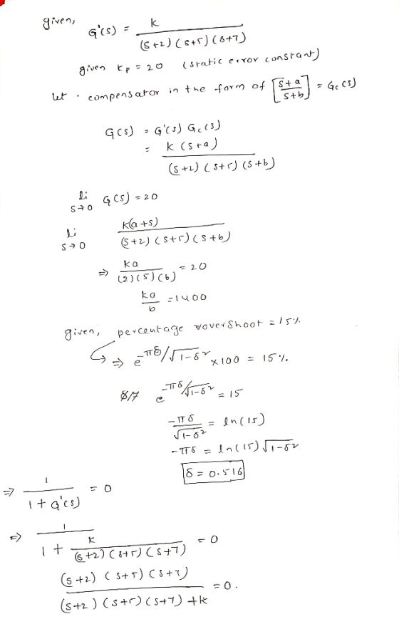
Problem 4 Suppose we have the system shown below operating at 15% overshoot. G(s)- (G) (s +2)%s +5%s+7) Use time domain techniques to design a compensator (and find K) so the appropriate static e...
Please answer this question showing all the steps. Problem 1 Suppose we have the system shown below operating at 1 0% overshoot. Go) +s+2)(+1 52 05123 120 Design changing the dominant pole locati...
 Please answer this question showing all the steps.
Problem 1 Suppose we have the system shown below operating at 1 0% overshoot. Go) +s+2)(+1 52 05123 120 Design changing the dominant pole locations of the uncompensated system a lag compensator so the appropriate static error constant is 5 without appreciably
Problem 1 Suppose we have the system shown below operating at 1 0% overshoot. Go) +s+2)(+1 52 05123 120 Design changing the dominant pole locations of the uncompensated system a...
Please answer this question showing all the steps.
Problem 1 Suppose we have the system shown below operating at 1 0% overshoot. Go) +s+2)(+1 52 05123 120 Design changing the dominant pole locations of the uncompensated system a lag compensator so the appropriate static error constant is 5 without appreciably
Problem 1 Suppose we have the system shown below operating at 1 0% overshoot. Go) +s+2)(+1 52 05123 120 Design changing the dominant pole locations of the uncompensated system a...
Problem (5): . The unity feedback system shown in Figure P9.1 with is operating with 10% overshoo...
 Problem (5): . The unity feedback system shown in Figure P9.1 with is operating with 10% overshoot [Section: 9 21 R. Whai is the value of the appropriate static error constant? b. Find the transfer function of a lag network so that the appropriale static error constant equals 4 without appreciably changing he dominant poles of the uncompensated system e. Use MATLAB or any other computer MATLAD progtam to si mulatcthe system o seethe effect of your compensator ML C(F)...
Design of PID compensator S. Design of PID (Proportional-plus-Integral and Derivative) Compensator ds/i (st3)(s+6 s+10) and...
 Design of PID compensator
S. Design of PID (Proportional-plus-Integral and Derivative) Compensator ds/i (st3)(s+6 s+10) and unity feedback Design a PID s+10) An uncompensated system has a gain controller so that the system can operate with a peak time that is two thirds that of the uncompensated system at 20% overshoot and with zero steady-state error for a step input. system has a gain Uncompensated system Compensated system K (s+8 G(s) = (s+3)(s+6)(s+10) ,H(s) = 1 20% OS; desired T,-23a...
Design of PID compensator
S. Design of PID (Proportional-plus-Integral and Derivative) Compensator ds/i (st3)(s+6 s+10) and unity feedback Design a PID s+10) An uncompensated system has a gain controller so that the system can operate with a peak time that is two thirds that of the uncompensated system at 20% overshoot and with zero steady-state error for a step input. system has a gain Uncompensated system Compensated system K (s+8 G(s) = (s+3)(s+6)(s+10) ,H(s) = 1 20% OS; desired T,-23a...
With explanation if possible, please 2. Design a lag compensator of the system in Figure 2 such that the static velocity error constant Kv is 40se ithout appreciably changing the original location (s...
 With explanation if possible, please
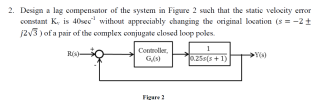
2. Design a lag compensator of the system in Figure 2 such that the static velocity error constant Kv is 40se ithout appreciably changing the original location (s--2+ j2V3) of a pair of the complex conjugate closed loop poles. Controller,0.25(S Ge(s) Figure 2
2. Design a lag compensator of the system in Figure 2 such that the static velocity error constant Kv is 40se ithout appreciably changing the original location (s--2+ j2V3) of a pair...
With explanation if possible, please
2. Design a lag compensator of the system in Figure 2 such that the static velocity error constant Kv is 40se ithout appreciably changing the original location (s--2+ j2V3) of a pair of the complex conjugate closed loop poles. Controller,0.25(S Ge(s) Figure 2
2. Design a lag compensator of the system in Figure 2 such that the static velocity error constant Kv is 40se ithout appreciably changing the original location (s--2+ j2V3) of a pair...
Please solve with detailed steps (NO MATLAB Solution).Thanks in advance 13. Consider the unity feedback system...
 Please solve with detailed steps (NO MATLAB
Solution).Thanks in advance
13. Consider the unity feedback system of Figure P9.1 with K G(s) s(s +20)(s +40) The system is operating at 20% overshoot. Design a compensator to decrease the settling time by a factor of 2 without affecting the percent overshoot and do the following: (Section: 9.3] a. Evaluate the uncompensated system's dominant poles, gain, and settling time. b. Evaluate the compensated system's dominant poles and settling time. c. Evaluate the...
Please solve with detailed steps (NO MATLAB
Solution).Thanks in advance
13. Consider the unity feedback system of Figure P9.1 with K G(s) s(s +20)(s +40) The system is operating at 20% overshoot. Design a compensator to decrease the settling time by a factor of 2 without affecting the percent overshoot and do the following: (Section: 9.3] a. Evaluate the uncompensated system's dominant poles, gain, and settling time. b. Evaluate the compensated system's dominant poles and settling time. c. Evaluate the...
Consider the sontrol system shown in the figure below: R(S) + E(s) C(s) K (s +...
 Consider the sontrol system shown in the figure below: R(S) + E(s) C(s) K (s + 4)(s + 6) g) Sketch the uncompensated system root locus showing all details. (5 Points) h) Find the dominant closed loop poles of the uncompensated system to operate with a 16.3% overshoot and peak time tp = 0.7255 (make sure to show this point on the Root Locus) (5 Points) (s+z) Now we want to design a PI compensator of the form to increase...
Find the dominant poles and gain K like they did in step 1 for the uncompensated system, EXCEPT D...
 Find the dominant poles and gain
K like they did in step 1 for the uncompensated
system, EXCEPT DO IT FOR 15% OVERSHOOT (zeta = 0.517) which is
121.13 degrees.
Show all work
Example 9.5 PID Controller Design PROBLEM: Given the system of Figure 9.31, design a PID controller so that the system can operate with a peak time that is two-thirds that of the uncompensated system at 20% overshoot and with zero steady-state error for a step input. R(s)Es)...
Find the dominant poles and gain
K like they did in step 1 for the uncompensated
system, EXCEPT DO IT FOR 15% OVERSHOOT (zeta = 0.517) which is
121.13 degrees.
Show all work
Example 9.5 PID Controller Design PROBLEM: Given the system of Figure 9.31, design a PID controller so that the system can operate with a peak time that is two-thirds that of the uncompensated system at 20% overshoot and with zero steady-state error for a step input. R(s)Es)...
For the control system shown below G(8) (8+10) 6+20) U(8) Y(8) H(s) = 1 design (using...
 For the control system shown below G(8) (8+10) 6+20) U(8) Y(8) H(s) = 1 design (using the Root-Locus Method) a compensator so that: • static velocity error constant K = 41 • the dumping ratio Efor dominant poles will remain unchanged, • a small change of undamped natural frequency oon is acceptable. sec For the control system shown below + G(S) = 820 s(8+10)(8+20) U(s) Y(s) H(s) = 1 design (using the Root-Locus Method) a LAG-LEAD compensator so that: •...
steps R(s) E(s) C(s) G(s) FIGURE P9.1 FIGURE P9.2 9. Consider the unity feedback system shown...
 steps
R(s) E(s) C(s) G(s) FIGURE P9.1 FIGURE P9.2 9. Consider the unity feedback system shown in Figure P9.1 with [Section: 9.3] K G(s) (s+4)3 a. Find the location of the dominant poles to yield a 1.6 second settling time and an overshoot of 25%. b. If a compensator with a zero at -1 is used to achieve the conditions of Part a, what must the angular contribution of the compensator pole be? c. Find the location of the compensator...
steps
R(s) E(s) C(s) G(s) FIGURE P9.1 FIGURE P9.2 9. Consider the unity feedback system shown in Figure P9.1 with [Section: 9.3] K G(s) (s+4)3 a. Find the location of the dominant poles to yield a 1.6 second settling time and an overshoot of 25%. b. If a compensator with a zero at -1 is used to achieve the conditions of Part a, what must the angular contribution of the compensator pole be? c. Find the location of the compensator...
Problem 4. Consider the control system shown below with plant G(s) that has time con- stants...
 Problem 4. Consider the control system shown below with plant G(s) that has time con- stants T1 = 2, T2 = 10, and gain k = 0.1. 4 673 +1679+1) (1.) Sketch the pole-zero plot for G(s). Is one of the poles more dominant? Using MATLAB, simulate the step response of the plant itself, along with G1(s) and G2(s) as defined by Gl(s) = and G2(s) = sti + 1 ST2+1 (2.) Design a proportional gain C(s) = K so...
 Please answer this question showing all the steps.
Problem 1 Suppose we have the system shown below operating at 1 0% overshoot. Go) +s+2)(+1 52 05123 120 Design changing the dominant pole locations of the uncompensated system a lag compensator so the appropriate static error constant is 5 without appreciably
Problem 1 Suppose we have the system shown below operating at 1 0% overshoot. Go) +s+2)(+1 52 05123 120 Design changing the dominant pole locations of the uncompensated system a...
Please answer this question showing all the steps.
Problem 1 Suppose we have the system shown below operating at 1 0% overshoot. Go) +s+2)(+1 52 05123 120 Design changing the dominant pole locations of the uncompensated system a lag compensator so the appropriate static error constant is 5 without appreciably
Problem 1 Suppose we have the system shown below operating at 1 0% overshoot. Go) +s+2)(+1 52 05123 120 Design changing the dominant pole locations of the uncompensated system a...
 Problem (5): . The unity feedback system shown in Figure P9.1 with is operating with 10% overshoot [Section: 9 21 R. Whai is the value of the appropriate static error constant? b. Find the transfer function of a lag network so that the appropriale static error constant equals 4 without appreciably changing he dominant poles of the uncompensated system e. Use MATLAB or any other computer MATLAD progtam to si mulatcthe system o seethe effect of your compensator ML C(F)...
 Design of PID compensator
S. Design of PID (Proportional-plus-Integral and Derivative) Compensator ds/i (st3)(s+6 s+10) and unity feedback Design a PID s+10) An uncompensated system has a gain controller so that the system can operate with a peak time that is two thirds that of the uncompensated system at 20% overshoot and with zero steady-state error for a step input. system has a gain Uncompensated system Compensated system K (s+8 G(s) = (s+3)(s+6)(s+10) ,H(s) = 1 20% OS; desired T,-23a...
Design of PID compensator
S. Design of PID (Proportional-plus-Integral and Derivative) Compensator ds/i (st3)(s+6 s+10) and unity feedback Design a PID s+10) An uncompensated system has a gain controller so that the system can operate with a peak time that is two thirds that of the uncompensated system at 20% overshoot and with zero steady-state error for a step input. system has a gain Uncompensated system Compensated system K (s+8 G(s) = (s+3)(s+6)(s+10) ,H(s) = 1 20% OS; desired T,-23a...
 With explanation if possible, please
2. Design a lag compensator of the system in Figure 2 such that the static velocity error constant Kv is 40se ithout appreciably changing the original location (s--2+ j2V3) of a pair of the complex conjugate closed loop poles. Controller,0.25(S Ge(s) Figure 2
2. Design a lag compensator of the system in Figure 2 such that the static velocity error constant Kv is 40se ithout appreciably changing the original location (s--2+ j2V3) of a pair...
With explanation if possible, please
2. Design a lag compensator of the system in Figure 2 such that the static velocity error constant Kv is 40se ithout appreciably changing the original location (s--2+ j2V3) of a pair of the complex conjugate closed loop poles. Controller,0.25(S Ge(s) Figure 2
2. Design a lag compensator of the system in Figure 2 such that the static velocity error constant Kv is 40se ithout appreciably changing the original location (s--2+ j2V3) of a pair...
 Please solve with detailed steps (NO MATLAB
Solution).Thanks in advance
13. Consider the unity feedback system of Figure P9.1 with K G(s) s(s +20)(s +40) The system is operating at 20% overshoot. Design a compensator to decrease the settling time by a factor of 2 without affecting the percent overshoot and do the following: (Section: 9.3] a. Evaluate the uncompensated system's dominant poles, gain, and settling time. b. Evaluate the compensated system's dominant poles and settling time. c. Evaluate the...
Please solve with detailed steps (NO MATLAB
Solution).Thanks in advance
13. Consider the unity feedback system of Figure P9.1 with K G(s) s(s +20)(s +40) The system is operating at 20% overshoot. Design a compensator to decrease the settling time by a factor of 2 without affecting the percent overshoot and do the following: (Section: 9.3] a. Evaluate the uncompensated system's dominant poles, gain, and settling time. b. Evaluate the compensated system's dominant poles and settling time. c. Evaluate the...
 Consider the sontrol system shown in the figure below: R(S) + E(s) C(s) K (s + 4)(s + 6) g) Sketch the uncompensated system root locus showing all details. (5 Points) h) Find the dominant closed loop poles of the uncompensated system to operate with a 16.3% overshoot and peak time tp = 0.7255 (make sure to show this point on the Root Locus) (5 Points) (s+z) Now we want to design a PI compensator of the form to increase...
 Find the dominant poles and gain
K like they did in step 1 for the uncompensated
system, EXCEPT DO IT FOR 15% OVERSHOOT (zeta = 0.517) which is
121.13 degrees.
Show all work
Example 9.5 PID Controller Design PROBLEM: Given the system of Figure 9.31, design a PID controller so that the system can operate with a peak time that is two-thirds that of the uncompensated system at 20% overshoot and with zero steady-state error for a step input. R(s)Es)...
Find the dominant poles and gain
K like they did in step 1 for the uncompensated
system, EXCEPT DO IT FOR 15% OVERSHOOT (zeta = 0.517) which is
121.13 degrees.
Show all work
Example 9.5 PID Controller Design PROBLEM: Given the system of Figure 9.31, design a PID controller so that the system can operate with a peak time that is two-thirds that of the uncompensated system at 20% overshoot and with zero steady-state error for a step input. R(s)Es)...
 For the control system shown below G(8) (8+10) 6+20) U(8) Y(8) H(s) = 1 design (using the Root-Locus Method) a compensator so that: • static velocity error constant K = 41 • the dumping ratio Efor dominant poles will remain unchanged, • a small change of undamped natural frequency oon is acceptable. sec For the control system shown below + G(S) = 820 s(8+10)(8+20) U(s) Y(s) H(s) = 1 design (using the Root-Locus Method) a LAG-LEAD compensator so that: •...
 steps
R(s) E(s) C(s) G(s) FIGURE P9.1 FIGURE P9.2 9. Consider the unity feedback system shown in Figure P9.1 with [Section: 9.3] K G(s) (s+4)3 a. Find the location of the dominant poles to yield a 1.6 second settling time and an overshoot of 25%. b. If a compensator with a zero at -1 is used to achieve the conditions of Part a, what must the angular contribution of the compensator pole be? c. Find the location of the compensator...
steps
R(s) E(s) C(s) G(s) FIGURE P9.1 FIGURE P9.2 9. Consider the unity feedback system shown in Figure P9.1 with [Section: 9.3] K G(s) (s+4)3 a. Find the location of the dominant poles to yield a 1.6 second settling time and an overshoot of 25%. b. If a compensator with a zero at -1 is used to achieve the conditions of Part a, what must the angular contribution of the compensator pole be? c. Find the location of the compensator...
 Problem 4. Consider the control system shown below with plant G(s) that has time con- stants T1 = 2, T2 = 10, and gain k = 0.1. 4 673 +1679+1) (1.) Sketch the pole-zero plot for G(s). Is one of the poles more dominant? Using MATLAB, simulate the step response of the plant itself, along with G1(s) and G2(s) as defined by Gl(s) = and G2(s) = sti + 1 ST2+1 (2.) Design a proportional gain C(s) = K so...
Most questions answered within 3 hours.
-
Where is the error in this code sequence?
String s1 = "Hello";
String s2 = "ello";...
asked 11 months ago -
Financial data for Joel de Paris, Inc., for last year
follow:
Joel de Paris, Inc.
Balance...
asked 11 months ago -
Consider this reaction:
Al2(SO4)3 (aq)+ BaCl3
(aq) Al2Cl6 (aq)- +
3BaSO4(s) . What is the...
asked 11 months ago -
Suppose that Savneet is considering increasing her
recent random sample from 20 car rentals to 40...
asked 11 months ago -
Trucks arrive at an unloading terminal at an average rate of 120
per hour.
Trucks arrive...
asked 11 months ago -
Why are methanol and ethanol completely soluble in water while
octanol is not very little soluble....
asked 11 months ago -
A facilities manager at a university reads in a research report
that the mean amount of...
asked 11 months ago -
When the CuSO4 is rehydrated by adding water to the anhydrous
compound, is this an endothermic...
asked 11 months ago -
A ray of sunlight is passing from diamond into crown glass; the
angle of incidence is...
asked 11 months ago -
A block of mass 0.249 kg is placed on top of a light, vertical
spring of...
asked 11 months ago -
how do the kidneys compensate in the presences of acidosis
a) trigger hyperventilate
b) reserve acid...
asked 11 months ago -
Question 501 pts
The rental rate of capital to the firm increases. Which of the
following...
asked 11 months ago