
Homework Answers

If you have any doubts please comment
Thank you
Add Answer to:
You are given the circuit below. Determine the current through the capacitor in phasor form You are given the circ...
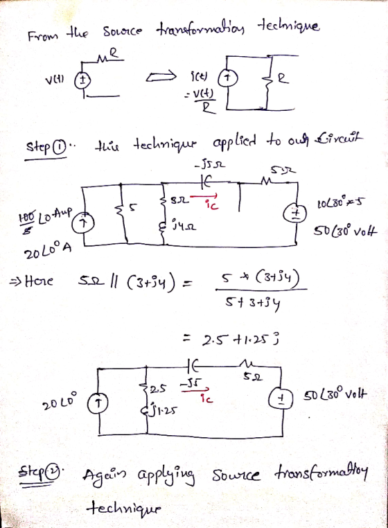
Part I: Derive the phasor relation for a capacitor starting from the equation that describes the...
 Part I: Derive the phasor relation for a capacitor starting from the equation that describes the current through a capacitor as a function of a voltage on a capacitor. Assume that the capacitance of the capacitor is C. (Hint: Starting from the time- domain relation and using Phasor transformation for current and voltage. prove that the impedance of capacitor is Part II: A parallel RC circuit is given. The circuit is driven by a sinusoidal current generator. Derive the phasor...
Determine the impedance of the load in phasor form.
 The waveforms below show the voltage measured across a complex load, and the current flowing through it. Use the information to determine the impedance of the load in phasor form.
In the circuit shown below, apply nodal analysis in the phasor domain to determine the current...
 In the circuit shown below, apply nodal analysis in the phasor domain to determine the current flowing out of the source on the right side, name it is (a) in phasor-domain, 1:1 (b) and in time-domain, is). 250 5923 ( 21 cos 105 V +1FMF 10.5 cos 101©
2502 In the adjoining circuit schematic, in steady-state, the current flowing through the loop causes a...
 2502 In the adjoining circuit schematic, in steady-state, the current flowing through the loop causes a voltage drop across the resistor, having the waveform vr(t) = 15 cos (75 t) and a voltage drop across the capacitor given by ve(t) = 20 cos (75 t +90°) (a) Express the above two voltages in phasor form. (b) Find the source voltage shown in the circuit schematic, expressed in phasor form. (c) Express the source voltage v(t) as a function of time....
In the adjoining circuit schematic, in steady-state, the current flowing through the loop causes a voltage...
 In the adjoining circuit schematic, in steady-state, the current
flowing through the loop causes a voltage drop across the resistor,
having the waveform
vR(t) = 15 cos (75 t) and a voltage drop across the capacitor
given by vC(t) = 20 cos (75 t + 90⁰)
(a) Express the above two voltages in phasor form. (b) Find the
source voltage shown in the circuit schematic, expressed in phasor
form. (c) Express the source voltage v(t) as a function of
time....
In the adjoining circuit schematic, in steady-state, the current
flowing through the loop causes a voltage drop across the resistor,
having the waveform
vR(t) = 15 cos (75 t) and a voltage drop across the capacitor
given by vC(t) = 20 cos (75 t + 90⁰)
(a) Express the above two voltages in phasor form. (b) Find the
source voltage shown in the circuit schematic, expressed in phasor
form. (c) Express the source voltage v(t) as a function of
time....
01 The capacitor in the circuit to the left below is initially uncharged. It is connected...
 01 The capacitor in the circuit to the left below is initially uncharged. It is connected to a voltage source that produces a voltage given to the right in the figure below. Plot the current through the capacitor as a function of time. Label your plot, write values and units it v(V) 10 HF 02 The switch in the circuit below is closed at time t 0 Sec. The initial voltage across the capacitor is zero. Find the current through...
For the series-parallel RL circuit shown below, determine: Total impedance in rectangular and phasor forms Find...
 For the series-parallel RL circuit shown below, determine: Total impedance in rectangular and phasor forms Find current passing through each components Find both voltages across the resistor and Inductors
3.The phasor diagrams for a series RLC circuit are shown below. Rank the frequencies from lowest ...
 3.The phasor diagrams for a series RLC circuit are shown below. Rank the frequencies from lowest to highest. Which frequency is closest to the resonance? a. b. VI Vt Vc 4. Circuit / has a reonant frequency of wy, What is the resonant frequency wn of circuit // in terms of w? Circuit L Circuit IT 2L C/2 ε sin(40t) & sin(ot) 5. At time t -0 the capacitor in the circult below is fully charged with Qmax and the...
Write the mesh equations for the following circuit and determine the current through and the volt...
 write the mesh equations for the following circuit and determine
the current through and the voltage across R1 (express the final
answer in phasor form)
E3= 40 V < 0degrees
12Ω 12Ω 3Ω 20 V 2 50°
12Ω 12Ω 3Ω 20 V 2 50°
write the mesh equations for the following circuit and determine
the current through and the voltage across R1 (express the final
answer in phasor form)
E3= 40 V < 0degrees
12Ω 12Ω 3Ω 20 V 2 50°
12Ω 12Ω 3Ω 20 V 2 50°
The next three problems refer to the circuit below. The phasor circuit is given; impedances are...
 The next three problems refer to the circuit below. The phasor
circuit is given; impedances are in Ohms and I and Vx represent
phasors I and Vx.
Question 15 (2 points) The next three problems refer to the circuit below. The phasor circuit is given; impedances are in Ohms and I and Vx represent phasors I and Vx- The voltage source is 10/0° V 5 j2 Vx + + 8Vx Which is a correct KVL equation for this circuit? -10...
The next three problems refer to the circuit below. The phasor
circuit is given; impedances are in Ohms and I and Vx represent
phasors I and Vx.
Question 15 (2 points) The next three problems refer to the circuit below. The phasor circuit is given; impedances are in Ohms and I and Vx represent phasors I and Vx- The voltage source is 10/0° V 5 j2 Vx + + 8Vx Which is a correct KVL equation for this circuit? -10...
 Part I: Derive the phasor relation for a capacitor starting from the equation that describes the current through a capacitor as a function of a voltage on a capacitor. Assume that the capacitance of the capacitor is C. (Hint: Starting from the time- domain relation and using Phasor transformation for current and voltage. prove that the impedance of capacitor is Part II: A parallel RC circuit is given. The circuit is driven by a sinusoidal current generator. Derive the phasor...
 In the circuit shown below, apply nodal analysis in the phasor domain to determine the current flowing out of the source on the right side, name it is (a) in phasor-domain, 1:1 (b) and in time-domain, is). 250 5923 ( 21 cos 105 V +1FMF 10.5 cos 101©
 2502 In the adjoining circuit schematic, in steady-state, the current flowing through the loop causes a voltage drop across the resistor, having the waveform vr(t) = 15 cos (75 t) and a voltage drop across the capacitor given by ve(t) = 20 cos (75 t +90°) (a) Express the above two voltages in phasor form. (b) Find the source voltage shown in the circuit schematic, expressed in phasor form. (c) Express the source voltage v(t) as a function of time....
 In the adjoining circuit schematic, in steady-state, the current
flowing through the loop causes a voltage drop across the resistor,
having the waveform
vR(t) = 15 cos (75 t) and a voltage drop across the capacitor
given by vC(t) = 20 cos (75 t + 90⁰)
(a) Express the above two voltages in phasor form. (b) Find the
source voltage shown in the circuit schematic, expressed in phasor
form. (c) Express the source voltage v(t) as a function of
time....
In the adjoining circuit schematic, in steady-state, the current
flowing through the loop causes a voltage drop across the resistor,
having the waveform
vR(t) = 15 cos (75 t) and a voltage drop across the capacitor
given by vC(t) = 20 cos (75 t + 90⁰)
(a) Express the above two voltages in phasor form. (b) Find the
source voltage shown in the circuit schematic, expressed in phasor
form. (c) Express the source voltage v(t) as a function of
time....
 01 The capacitor in the circuit to the left below is initially uncharged. It is connected to a voltage source that produces a voltage given to the right in the figure below. Plot the current through the capacitor as a function of time. Label your plot, write values and units it v(V) 10 HF 02 The switch in the circuit below is closed at time t 0 Sec. The initial voltage across the capacitor is zero. Find the current through...
 For the series-parallel RL circuit shown below, determine: Total impedance in rectangular and phasor forms Find current passing through each components Find both voltages across the resistor and Inductors
 3.The phasor diagrams for a series RLC circuit are shown below. Rank the frequencies from lowest to highest. Which frequency is closest to the resonance? a. b. VI Vt Vc 4. Circuit / has a reonant frequency of wy, What is the resonant frequency wn of circuit // in terms of w? Circuit L Circuit IT 2L C/2 ε sin(40t) & sin(ot) 5. At time t -0 the capacitor in the circult below is fully charged with Qmax and the...
 write the mesh equations for the following circuit and determine
the current through and the voltage across R1 (express the final
answer in phasor form)
E3= 40 V < 0degrees
12Ω 12Ω 3Ω 20 V 2 50°
12Ω 12Ω 3Ω 20 V 2 50°
write the mesh equations for the following circuit and determine
the current through and the voltage across R1 (express the final
answer in phasor form)
E3= 40 V < 0degrees
12Ω 12Ω 3Ω 20 V 2 50°
12Ω 12Ω 3Ω 20 V 2 50°
 The next three problems refer to the circuit below. The phasor
circuit is given; impedances are in Ohms and I and Vx represent
phasors I and Vx.
Question 15 (2 points) The next three problems refer to the circuit below. The phasor circuit is given; impedances are in Ohms and I and Vx represent phasors I and Vx- The voltage source is 10/0° V 5 j2 Vx + + 8Vx Which is a correct KVL equation for this circuit? -10...
The next three problems refer to the circuit below. The phasor
circuit is given; impedances are in Ohms and I and Vx represent
phasors I and Vx.
Question 15 (2 points) The next three problems refer to the circuit below. The phasor circuit is given; impedances are in Ohms and I and Vx represent phasors I and Vx- The voltage source is 10/0° V 5 j2 Vx + + 8Vx Which is a correct KVL equation for this circuit? -10...
Most questions answered within 3 hours.
-
Where is the error in this code sequence?
String s1 = "Hello";
String s2 = "ello";...
asked 10 months ago -
Financial data for Joel de Paris, Inc., for last year
follow:
Joel de Paris, Inc.
Balance...
asked 10 months ago -
Consider this reaction:
Al2(SO4)3 (aq)+ BaCl3
(aq) Al2Cl6 (aq)- +
3BaSO4(s) . What is the...
asked 10 months ago -
Suppose that Savneet is considering increasing her
recent random sample from 20 car rentals to 40...
asked 10 months ago -
Trucks arrive at an unloading terminal at an average rate of 120
per hour.
Trucks arrive...
asked 10 months ago -
Why are methanol and ethanol completely soluble in water while
octanol is not very little soluble....
asked 10 months ago -
A facilities manager at a university reads in a research report
that the mean amount of...
asked 10 months ago -
When the CuSO4 is rehydrated by adding water to the anhydrous
compound, is this an endothermic...
asked 10 months ago -
A ray of sunlight is passing from diamond into crown glass; the
angle of incidence is...
asked 10 months ago -
A block of mass 0.249 kg is placed on top of a light, vertical
spring of...
asked 10 months ago -
how do the kidneys compensate in the presences of acidosis
a) trigger hyperventilate
b) reserve acid...
asked 10 months ago -
Question 501 pts
The rental rate of capital to the firm increases. Which of the
following...
asked 10 months ago