
Homework Answers
Add Answer to:
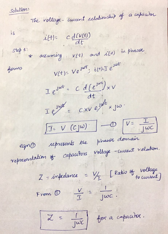
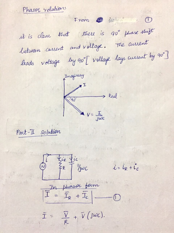
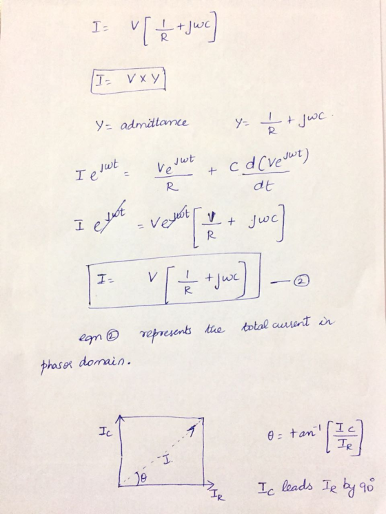
Part I: Derive the phasor relation for a capacitor starting from the equation that describes the...
Review Part A. Find the relationship between the phasor voltage and phasor current for a resistance...
 Review Part A. Find the relationship between the phasor voltage and phasor current for a resistance The resistor shown here has been transformed into the phasor domain: Ik 4k Suppose that the phasor current is given by IR = 752120 mA. Find the phasor voltage VR. Enter a complex number in polar form, with phase angle in degrees. View Available Hint(s) 3002120 V Submit Previous Answers Correct Part B - Draw the phasor diagram of the resistance from Part A...
or practice) Describe the sinusoidal waveforms shown in the figures, using time-dependen notation: a) (4-44) (part...
 or practice) Describe the sinusoidal waveforms shown in the figures, using time-dependen notation: a) (4-44) (part a is for practice) b) (4-44) (rads 2 P3. (4.48) Determine the equivalent impedance in the circuit shown, given that v(t) 636 cos(3,000t +t/12), L=1.90 H C=6.8 nF P4. (4-49) In the circuit shows (for practice). given that is(t) lo cos(wt + π/6). l, 13 mA. 1,000 rad/s, C = 0.5 μF. a) State, using phasor notation, the source current, b) Determine the impedance...
The two circuits you will model in Multisim and then build on the protoboard are the...
 The two circuits you will model in Multisim and then build on the protoboard are the RC and RL circuits shown in Figures 5 and 6 below. In all cases, make the voltage supply the time reference voltage as indicated in Equation 18 (18) Keep in mind that Vso and o will not be the same for both circuits. The RC Circuit The RC Circuit is shown in Figure 5. The capacitor will have a sinusoidal voltage drop given by...
Problem 24: (18 points) 1. (6 points) Figure 2 shows an RC circuit with input f(t)...
 Problem 24: (18 points) 1. (6 points) Figure 2 shows an RC circuit with input f(t) and output y(t) Function Generator R, v, (r) y1) Figure 2: RC circuit. (a) (1 point) Sketch the circuit in the phasor domain by replacing the capacitor with its impedance represen- (b) (3 points) Using circuit analysis techniques, show that the frequency response function is Specify the DC gain, K, and the time constant, T, in terms of the parameters R, R, and C...
Part C is wrong! is not 0.352!!! please help A resistor and capacitor are connected in...
 Part C is wrong! is not 0.352!!! please help
A resistor and capacitor are connected in series across an ac generator. The voltage of the generator is given by V(t) = Vocos(wt), where V. = 120V, w = 1204 rad/s, R= 800N, and C =9uF. (a) What is the magnitude of the impedance of the RC circuit? (b) What is the amplitude of the current through the resistor? (c) What is the phase difference between the voltage and current? The...
Part C is wrong! is not 0.352!!! please help
A resistor and capacitor are connected in series across an ac generator. The voltage of the generator is given by V(t) = Vocos(wt), where V. = 120V, w = 1204 rad/s, R= 800N, and C =9uF. (a) What is the magnitude of the impedance of the RC circuit? (b) What is the amplitude of the current through the resistor? (c) What is the phase difference between the voltage and current? The...
Derive time dependence of voltage and current for a capacitor equation v(t)=V(1-e-t/RC) i(t)=(V/R)(e-t/RC)
Derive time dependence of voltage and current for a capacitor equation v(t)=V(1-e-t/RC) i(t)=(V/R)(e-t/RC)
TASK (i): Find time-domain equations for a parallel LC resonant circuit An LC resonant circuit is...
 TASK (i): Find time-domain equations for a parallel LC resonant circuit An LC resonant circuit is sometimes referred to as an LC-tank or tuned circuit. It is made up of two components: an inductor (L) and a capacitor (C), hence the name. CAPACITOR 4 e V - + V - Figure 1: Capacitor symbol The charge on a capacitor is proportional to the voltage across it, the constant of proportionality being the capacitance C, measured in Farads (F). Since current...
Find the Steady State Voltage and Current Values. Develop the equation for i(t) , the current thr...
 Find the Steady State Voltage and Current
Values.
Develop the equation for i(t) , the current through
the inductor and Vout(t).
I need help, I don't know if my calculations are correct, I
found the neper frequency to be: a=439.109 rad/sec and resonant
frequency to be Wo=14586.5 rad/sec.
This is a parallel step response RLC circuit
The circuit is underdamped.
Please show all work clearly so that I can understand the
process.
Vout(t) is the voltage across R2 (which is...
Find the Steady State Voltage and Current
Values.
Develop the equation for i(t) , the current through
the inductor and Vout(t).
I need help, I don't know if my calculations are correct, I
found the neper frequency to be: a=439.109 rad/sec and resonant
frequency to be Wo=14586.5 rad/sec.
This is a parallel step response RLC circuit
The circuit is underdamped.
Please show all work clearly so that I can understand the
process.
Vout(t) is the voltage across R2 (which is...
1. Calculate (a) 24 + j5 + 16+ j10 (b) (4+ j12) x (4 – j12)...
 1. Calculate (a) 24 + j5 + 16+ j10 (b) (4+ j12) x (4 – j12) (c) (4+ j12) + (4 – j12) (d) Convert to rectangular form: 12/10°, 4.242-45° 2. Multiply and Divide the following polar form (a) 45224° x 10454° (b) 184-64° x 42-14° (c) 45224° ÷ 102-10° (d) 5002-72° ÷ 52-12° 150 cos(314t) volts is applied to a pure resistor of R = 30 N 3. A voltage v = (a) Write the expression for i as...
PLEASE SOLVE QUESTION NUMBER 2 ONLY, MAKE SURE ALL PARTS IN QUESTION 2 ARE SOLVED. THANK...
 PLEASE SOLVE QUESTION NUMBER 2 ONLY, MAKE SURE ALL PARTS IN
QUESTION 2 ARE SOLVED. THANK YOU
poirmts) l'igure output y ws an RG circuit with inpu Function Generator Model Capacitor Model i,(t) Figure 2: RC cireuit (a) (1 point) Sketch the circuit in the phasor domain by replacing the capacitor with its impedance represen- tation (b) (3 points) Using circuit analysis techniques, show that the frequency response function is F(u) UT 1 Specify the DC gain, K, and time...
PLEASE SOLVE QUESTION NUMBER 2 ONLY, MAKE SURE ALL PARTS IN
QUESTION 2 ARE SOLVED. THANK YOU
poirmts) l'igure output y ws an RG circuit with inpu Function Generator Model Capacitor Model i,(t) Figure 2: RC cireuit (a) (1 point) Sketch the circuit in the phasor domain by replacing the capacitor with its impedance represen- tation (b) (3 points) Using circuit analysis techniques, show that the frequency response function is F(u) UT 1 Specify the DC gain, K, and time...
 Review Part A. Find the relationship between the phasor voltage and phasor current for a resistance The resistor shown here has been transformed into the phasor domain: Ik 4k Suppose that the phasor current is given by IR = 752120 mA. Find the phasor voltage VR. Enter a complex number in polar form, with phase angle in degrees. View Available Hint(s) 3002120 V Submit Previous Answers Correct Part B - Draw the phasor diagram of the resistance from Part A...
 or practice) Describe the sinusoidal waveforms shown in the figures, using time-dependen notation: a) (4-44) (part a is for practice) b) (4-44) (rads 2 P3. (4.48) Determine the equivalent impedance in the circuit shown, given that v(t) 636 cos(3,000t +t/12), L=1.90 H C=6.8 nF P4. (4-49) In the circuit shows (for practice). given that is(t) lo cos(wt + π/6). l, 13 mA. 1,000 rad/s, C = 0.5 μF. a) State, using phasor notation, the source current, b) Determine the impedance...
 The two circuits you will model in Multisim and then build on the protoboard are the RC and RL circuits shown in Figures 5 and 6 below. In all cases, make the voltage supply the time reference voltage as indicated in Equation 18 (18) Keep in mind that Vso and o will not be the same for both circuits. The RC Circuit The RC Circuit is shown in Figure 5. The capacitor will have a sinusoidal voltage drop given by...
 Problem 24: (18 points) 1. (6 points) Figure 2 shows an RC circuit with input f(t) and output y(t) Function Generator R, v, (r) y1) Figure 2: RC circuit. (a) (1 point) Sketch the circuit in the phasor domain by replacing the capacitor with its impedance represen- (b) (3 points) Using circuit analysis techniques, show that the frequency response function is Specify the DC gain, K, and the time constant, T, in terms of the parameters R, R, and C...
 Part C is wrong! is not 0.352!!! please help
A resistor and capacitor are connected in series across an ac generator. The voltage of the generator is given by V(t) = Vocos(wt), where V. = 120V, w = 1204 rad/s, R= 800N, and C =9uF. (a) What is the magnitude of the impedance of the RC circuit? (b) What is the amplitude of the current through the resistor? (c) What is the phase difference between the voltage and current? The...
Part C is wrong! is not 0.352!!! please help
A resistor and capacitor are connected in series across an ac generator. The voltage of the generator is given by V(t) = Vocos(wt), where V. = 120V, w = 1204 rad/s, R= 800N, and C =9uF. (a) What is the magnitude of the impedance of the RC circuit? (b) What is the amplitude of the current through the resistor? (c) What is the phase difference between the voltage and current? The...
 TASK (i): Find time-domain equations for a parallel LC resonant circuit An LC resonant circuit is sometimes referred to as an LC-tank or tuned circuit. It is made up of two components: an inductor (L) and a capacitor (C), hence the name. CAPACITOR 4 e V - + V - Figure 1: Capacitor symbol The charge on a capacitor is proportional to the voltage across it, the constant of proportionality being the capacitance C, measured in Farads (F). Since current...
 Find the Steady State Voltage and Current
Values.
Develop the equation for i(t) , the current through
the inductor and Vout(t).
I need help, I don't know if my calculations are correct, I
found the neper frequency to be: a=439.109 rad/sec and resonant
frequency to be Wo=14586.5 rad/sec.
This is a parallel step response RLC circuit
The circuit is underdamped.
Please show all work clearly so that I can understand the
process.
Vout(t) is the voltage across R2 (which is...
Find the Steady State Voltage and Current
Values.
Develop the equation for i(t) , the current through
the inductor and Vout(t).
I need help, I don't know if my calculations are correct, I
found the neper frequency to be: a=439.109 rad/sec and resonant
frequency to be Wo=14586.5 rad/sec.
This is a parallel step response RLC circuit
The circuit is underdamped.
Please show all work clearly so that I can understand the
process.
Vout(t) is the voltage across R2 (which is...
 1. Calculate (a) 24 + j5 + 16+ j10 (b) (4+ j12) x (4 – j12) (c) (4+ j12) + (4 – j12) (d) Convert to rectangular form: 12/10°, 4.242-45° 2. Multiply and Divide the following polar form (a) 45224° x 10454° (b) 184-64° x 42-14° (c) 45224° ÷ 102-10° (d) 5002-72° ÷ 52-12° 150 cos(314t) volts is applied to a pure resistor of R = 30 N 3. A voltage v = (a) Write the expression for i as...
 PLEASE SOLVE QUESTION NUMBER 2 ONLY, MAKE SURE ALL PARTS IN
QUESTION 2 ARE SOLVED. THANK YOU
poirmts) l'igure output y ws an RG circuit with inpu Function Generator Model Capacitor Model i,(t) Figure 2: RC cireuit (a) (1 point) Sketch the circuit in the phasor domain by replacing the capacitor with its impedance represen- tation (b) (3 points) Using circuit analysis techniques, show that the frequency response function is F(u) UT 1 Specify the DC gain, K, and time...
PLEASE SOLVE QUESTION NUMBER 2 ONLY, MAKE SURE ALL PARTS IN
QUESTION 2 ARE SOLVED. THANK YOU
poirmts) l'igure output y ws an RG circuit with inpu Function Generator Model Capacitor Model i,(t) Figure 2: RC cireuit (a) (1 point) Sketch the circuit in the phasor domain by replacing the capacitor with its impedance represen- tation (b) (3 points) Using circuit analysis techniques, show that the frequency response function is F(u) UT 1 Specify the DC gain, K, and time...
Most questions answered within 3 hours.
-
Where is the error in this code sequence?
String s1 = "Hello";
String s2 = "ello";...
asked 11 months ago -
Financial data for Joel de Paris, Inc., for last year
follow:
Joel de Paris, Inc.
Balance...
asked 11 months ago -
Consider this reaction:
Al2(SO4)3 (aq)+ BaCl3
(aq) Al2Cl6 (aq)- +
3BaSO4(s) . What is the...
asked 11 months ago -
Suppose that Savneet is considering increasing her
recent random sample from 20 car rentals to 40...
asked 11 months ago -
Trucks arrive at an unloading terminal at an average rate of 120
per hour.
Trucks arrive...
asked 11 months ago -
Why are methanol and ethanol completely soluble in water while
octanol is not very little soluble....
asked 11 months ago -
A facilities manager at a university reads in a research report
that the mean amount of...
asked 11 months ago -
When the CuSO4 is rehydrated by adding water to the anhydrous
compound, is this an endothermic...
asked 11 months ago -
A ray of sunlight is passing from diamond into crown glass; the
angle of incidence is...
asked 11 months ago -
A block of mass 0.249 kg is placed on top of a light, vertical
spring of...
asked 11 months ago -
how do the kidneys compensate in the presences of acidosis
a) trigger hyperventilate
b) reserve acid...
asked 11 months ago -
Question 501 pts
The rental rate of capital to the firm increases. Which of the
following...
asked 11 months ago