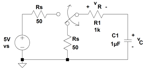
Consider the circuit of Figure 1. The voltage source vs and resistance Rs comprise a circuit model of a function generator.
1. Find the circuit time constant ? for t?0. Assuming that the capacitor is initially uncharged, find and accurately sketch vR(t) and vC(t) for t?0. Calculate vR(t) and vC(t) for t = 0, ?, 2?, 3?, 4?, and 5? seconds.
2. Find the 10-90% rise time of vC(t) (this is the time required for vC(t) to transition from 10% (0.5V) to 90% (4.5V) of its final value).
Homework Answers


Add Answer to:
Consider the circuit of Figure 1. The voltage source vs and
resistance Rs comprise a circuit model of a function genera...
Consider the circuit of Figure 1. The voltage source Vs and resistance Rs comprise a circuit model of a function g...
 Consider the circuit of Figure 1. The voltage source Vs and
resistance Rs comprise a circuit model of a function
generator.
Find the circuit time constant τ for t≥0. Assuming that the
capacitor is initially uncharged, find and accurately sketch vR(t)
and vC(t) for t≥0. Calculate vR(t) and vC(t) for t = 0, τ, 2τ, 3τ,
4τ, and 5τ seconds.
Find the 10-90% rise time of vC(t) (this is the time required for
vC(t) to transition from 10% (0.5V) to...
Consider the circuit of Figure 1. The voltage source Vs and
resistance Rs comprise a circuit model of a function
generator.
Find the circuit time constant τ for t≥0. Assuming that the
capacitor is initially uncharged, find and accurately sketch vR(t)
and vC(t) for t≥0. Calculate vR(t) and vC(t) for t = 0, τ, 2τ, 3τ,
4τ, and 5τ seconds.
Find the 10-90% rise time of vC(t) (this is the time required for
vC(t) to transition from 10% (0.5V) to...
Consider the series RLC circuit in Figure 1. Suppose the source voltage is initially OV, and...
 Consider the series RLC circuit in Figure 1. Suppose the source voltage is initially OV, and no energy is stored in both the capacitor and inductor. At t = 0, the source voltage is switched to 1V. Calculate the resistor, inductor and capacitor voltages, and the loop current V (t),,(t),Vc(t),i(t). Show all the steps. C1 L1 1.2u 8.2m 10 3 R1 Figure 1: A series RLC circuit
Consider the simple series RLC circuit shown in figure below, the circuit has the following parameters,...
 Consider the simple series RLC circuit shown in figure below, the circuit has the following parameters, R=12, L = 0.2 Henry, and C = 0.05 Farad, R 1000 Vs The system is governed by the following equations: V = VR + V + V VR = IR V = Vc S(t)dt Or I = CM Construct a Simulink model for this system such that the input is the supply voltage Vs and the output is the voltage across the resistor...
A series circuit has a DC voltage source (42 volts), a resistor (70 ohms), a capacitor...
A series circuit has a DC voltage source (42 volts), a resistor (70 ohms), a capacitor (25 farads), and a switch. The capacitor is initially uncharged and the switch closes at t=0. Sketch the exponential current and capacitor voltage: i(t)=Aexp(-t/tau) +B, and Vc(t)=Dexp(-t/tau) +F. Find: A,B,D,F,tau,i(t=tau),i(t=4tau),Vc(t=tau),and Vc(t=3tau).
A series circuit has a DC voltage source (73 volts), a resistor (95 ohms), a capacitor...
A series circuit has a DC voltage source (73 volts), a resistor (95 ohms), a capacitor (91 farads), and a switch. The capacitor is initially uncharged and the switch closes at t=0. Sketch the exponential current and capacitor voltage: i(t)=Aexp(-t/tau) +B, and Vc(t)=Dexp(-t/tau) +F. Find: A,B,D,F,tau,i(t=tau),i(t=4tau),Vc(t=tau),and Vc(t=3tau).
Inductor +VR 300 220m 100 50 LI Function Generator Figure 2: RLC Circuit with 100Ω Resistor Ind...
 Please help answer in pspice, thank you very much.
Inductor +VR 300 220m 100 50 LI Function Generator Figure 2: RLC Circuit with 100Ω Resistor Inductor 50 300 220m 1k Function Generator Figure 1: RLC Circuit with 1kQ Resistor Generate a computer simulation modeling the capacitor voltage transient of the RLC circuit for Figures 1 and 2. Measure the initial capacitor voltage, vc(0), the final capacitor voltage, vc), and the capacitor voltage at 0.5 mS, 1 mS, and 2 mS....
Please help answer in pspice, thank you very much.
Inductor +VR 300 220m 100 50 LI Function Generator Figure 2: RLC Circuit with 100Ω Resistor Inductor 50 300 220m 1k Function Generator Figure 1: RLC Circuit with 1kQ Resistor Generate a computer simulation modeling the capacitor voltage transient of the RLC circuit for Figures 1 and 2. Measure the initial capacitor voltage, vc(0), the final capacitor voltage, vc), and the capacitor voltage at 0.5 mS, 1 mS, and 2 mS....
Problem 1 100000 Ohms Consider the RC circuit on the right. and suppose that Vs(t) is a time-vary...
 Problem 1 100000 Ohms Consider the RC circuit on the right. and suppose that Vs(t) is a time-varying voltage input shown at the bottom VR(t) vC(t) Vs(t) 1 uF a) Suppose VC(0) OV. Plot VR(t) and VC(t) from ms to 300ms. Show your work in obtaining VR(t) and VC(t). b) Suppose the capacitance value is changed to 2μF, and VC(0) 0V. Plot VR(t) and VC(t) from Oms to 300ms. Show your work in obtaining VR(t) and VC(t). Vs(t) 1V c)...
Function Generatr Inductor Model Ra R, Figure 1 Series RLC Circuit Preliminary This laboratory wi...
 Function Generatr Inductor Model Ra R, Figure 1 Series RLC Circuit Preliminary This laboratory will demonstrate how varying resistance changes the natural response of a series RLC circuit (Fig. 1). The function generator is modeled as an ideal voltage source v(t) 5 u() V in series with source resistance Rs-50Q. After measurements using an LCR meter, the inductor is modeled as an ideal L 90 mH inductor in series with resistance RL-20Q. The capacitance is C-0.22 μF. 1) Calculate the...
R + 1. Analyze the following circuit. Calculate the capacitor voltage as a function of time...
 R + 1. Analyze the following circuit. Calculate the capacitor voltage as a function of time for 5V step input. (R=1k, C=200nF). Assume initial capacitor voltage is zero. (5%) 2. Simulate the circuit in the figure with the parameters in your lab document" Put the schematic. (5%) Transient Simulation result -10% + vs(t) RS vc(t) С an 3. Search internet, choose application circuit that will generate square wave oscillation using LM555. Adjust the frequency by properly selecting R and C...
 Consider the circuit of Figure 1. The voltage source Vs and
resistance Rs comprise a circuit model of a function
generator.
Find the circuit time constant τ for t≥0. Assuming that the
capacitor is initially uncharged, find and accurately sketch vR(t)
and vC(t) for t≥0. Calculate vR(t) and vC(t) for t = 0, τ, 2τ, 3τ,
4τ, and 5τ seconds.
Find the 10-90% rise time of vC(t) (this is the time required for
vC(t) to transition from 10% (0.5V) to...
Consider the circuit of Figure 1. The voltage source Vs and
resistance Rs comprise a circuit model of a function
generator.
Find the circuit time constant τ for t≥0. Assuming that the
capacitor is initially uncharged, find and accurately sketch vR(t)
and vC(t) for t≥0. Calculate vR(t) and vC(t) for t = 0, τ, 2τ, 3τ,
4τ, and 5τ seconds.
Find the 10-90% rise time of vC(t) (this is the time required for
vC(t) to transition from 10% (0.5V) to...
 Consider the series RLC circuit in Figure 1. Suppose the source voltage is initially OV, and no energy is stored in both the capacitor and inductor. At t = 0, the source voltage is switched to 1V. Calculate the resistor, inductor and capacitor voltages, and the loop current V (t),,(t),Vc(t),i(t). Show all the steps. C1 L1 1.2u 8.2m 10 3 R1 Figure 1: A series RLC circuit
 Consider the simple series RLC circuit shown in figure below, the circuit has the following parameters, R=12, L = 0.2 Henry, and C = 0.05 Farad, R 1000 Vs The system is governed by the following equations: V = VR + V + V VR = IR V = Vc S(t)dt Or I = CM Construct a Simulink model for this system such that the input is the supply voltage Vs and the output is the voltage across the resistor...
 Please help answer in pspice, thank you very much.
Inductor +VR 300 220m 100 50 LI Function Generator Figure 2: RLC Circuit with 100Ω Resistor Inductor 50 300 220m 1k Function Generator Figure 1: RLC Circuit with 1kQ Resistor Generate a computer simulation modeling the capacitor voltage transient of the RLC circuit for Figures 1 and 2. Measure the initial capacitor voltage, vc(0), the final capacitor voltage, vc), and the capacitor voltage at 0.5 mS, 1 mS, and 2 mS....
Please help answer in pspice, thank you very much.
Inductor +VR 300 220m 100 50 LI Function Generator Figure 2: RLC Circuit with 100Ω Resistor Inductor 50 300 220m 1k Function Generator Figure 1: RLC Circuit with 1kQ Resistor Generate a computer simulation modeling the capacitor voltage transient of the RLC circuit for Figures 1 and 2. Measure the initial capacitor voltage, vc(0), the final capacitor voltage, vc), and the capacitor voltage at 0.5 mS, 1 mS, and 2 mS....
 Problem 1 100000 Ohms Consider the RC circuit on the right. and suppose that Vs(t) is a time-varying voltage input shown at the bottom VR(t) vC(t) Vs(t) 1 uF a) Suppose VC(0) OV. Plot VR(t) and VC(t) from ms to 300ms. Show your work in obtaining VR(t) and VC(t). b) Suppose the capacitance value is changed to 2μF, and VC(0) 0V. Plot VR(t) and VC(t) from Oms to 300ms. Show your work in obtaining VR(t) and VC(t). Vs(t) 1V c)...
 Function Generatr Inductor Model Ra R, Figure 1 Series RLC Circuit Preliminary This laboratory will demonstrate how varying resistance changes the natural response of a series RLC circuit (Fig. 1). The function generator is modeled as an ideal voltage source v(t) 5 u() V in series with source resistance Rs-50Q. After measurements using an LCR meter, the inductor is modeled as an ideal L 90 mH inductor in series with resistance RL-20Q. The capacitance is C-0.22 μF. 1) Calculate the...
 R + 1. Analyze the following circuit. Calculate the capacitor voltage as a function of time for 5V step input. (R=1k, C=200nF). Assume initial capacitor voltage is zero. (5%) 2. Simulate the circuit in the figure with the parameters in your lab document" Put the schematic. (5%) Transient Simulation result -10% + vs(t) RS vc(t) С an 3. Search internet, choose application circuit that will generate square wave oscillation using LM555. Adjust the frequency by properly selecting R and C...
Most questions answered within 3 hours.
-
Where is the error in this code sequence?
String s1 = "Hello";
String s2 = "ello";...
asked 11 months ago -
Financial data for Joel de Paris, Inc., for last year
follow:
Joel de Paris, Inc.
Balance...
asked 11 months ago -
Consider this reaction:
Al2(SO4)3 (aq)+ BaCl3
(aq) Al2Cl6 (aq)- +
3BaSO4(s) . What is the...
asked 11 months ago -
Suppose that Savneet is considering increasing her
recent random sample from 20 car rentals to 40...
asked 11 months ago -
Trucks arrive at an unloading terminal at an average rate of 120
per hour.
Trucks arrive...
asked 11 months ago -
Why are methanol and ethanol completely soluble in water while
octanol is not very little soluble....
asked 11 months ago -
A facilities manager at a university reads in a research report
that the mean amount of...
asked 11 months ago -
When the CuSO4 is rehydrated by adding water to the anhydrous
compound, is this an endothermic...
asked 11 months ago -
A ray of sunlight is passing from diamond into crown glass; the
angle of incidence is...
asked 11 months ago -
A block of mass 0.249 kg is placed on top of a light, vertical
spring of...
asked 11 months ago -
how do the kidneys compensate in the presences of acidosis
a) trigger hyperventilate
b) reserve acid...
asked 11 months ago -
Question 501 pts
The rental rate of capital to the firm increases. Which of the
following...
asked 11 months ago