
Homework Answers
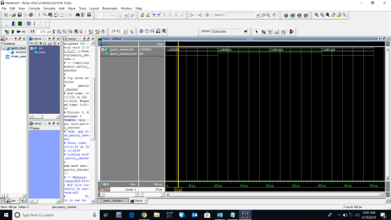
module parity_checker (din, even);
input [7:0] din;
output even;
assign even = ~(din[7] ^ din[6] ^ din[5] ^ din[4] ^ din[3] ^ din[2] ^ din[1] ^ din[0]);
endmodule
//////////////////////////////////////////////////////////////////////////////////////////////////////////////////////////////////////////////////////////////////////////////////
Add Answer to:
Please include waveform Experiment #1 Design and create simulation waveform for an 8-bit even parity checker using V...
Experiment #3 Design and create simulation waveform for an 8-bit up/down synchronous (rising edge of clock) binary coun...
 Experiment #3 Design and create simulation waveform for an 8-bit up/down synchronous (rising edge of clock) binary counter using Verilog Remember that your testbench can include statements such as always begin #10 clock="clock; end which specifies that the clock (reg) should toggle every 10 nSec
Experiment #3 Design and create simulation waveform for an 8-bit up/down synchronous (rising edge of clock) binary counter using Verilog Remember that your testbench can include statements such as always begin #10 clock="clock; end which...
Experiment #3 Design and create simulation waveform for an 8-bit up/down synchronous (rising edge of clock) binary counter using Verilog Remember that your testbench can include statements such as always begin #10 clock="clock; end which specifies that the clock (reg) should toggle every 10 nSec
Experiment #3 Design and create simulation waveform for an 8-bit up/down synchronous (rising edge of clock) binary counter using Verilog Remember that your testbench can include statements such as always begin #10 clock="clock; end which...
Experiment #4 Design and create a simulation waveform for a 5 out of 16 event detector using Verilog. This system w...
 Experiment #4 Design and create a simulation waveform for a 5 out of 16 event detector using Verilog. This system will assert output to 1 when exactly 5 out of the last 16 serial events (value of input at the rising edges of clock) have been 1s. Here is an example timing diagram: CLK IN 1 2 3 4 6 OUT
Experiment #4 Design and create a simulation waveform for a 5 out of 16 event detector using Verilog. This...
Experiment #4 Design and create a simulation waveform for a 5 out of 16 event detector using Verilog. This system will assert output to 1 when exactly 5 out of the last 16 serial events (value of input at the rising edges of clock) have been 1s. Here is an example timing diagram: CLK IN 1 2 3 4 6 OUT
Experiment #4 Design and create a simulation waveform for a 5 out of 16 event detector using Verilog. This...
⦁ Parity Checker Design a parity checker circuit: PC(D2, D1, D0, OP). The inputs D2, D1,...
⦁ Parity Checker Design a parity checker circuit: PC(D2, D1, D0, OP). The inputs D2, D1, D0, OP represent the bits of the received message. The inputs D2, D1, D0 are the data message and the input OP is the parity bit that was generated by an odd parity generator. If the parity of the received message is correct, the output PC is a zero. If the parity of the received message is not correct, the circuit output PC is...
Extra problem: Use the attached sheet to draw a 8- bit odd parity generator and a...
 Extra problem: Use the attached sheet to draw a 8- bit odd parity generator and a odd-parity checker for the 8 data bits and odd parity bit. Let the Error output be active-low (so that it goes low if there is an error and is high if there is no error) Parity Error-Detection System Using 74280s, design a complete parity generator/checking system. It is to be used in an 8-bit, even-parity computer configuration. Solution: Parity generator: Because the 74280 has...
VHDL structural code please Design an 8-bit add/subtract in Verilog AND VHDL using any of the...
 VHDL structural code please
Design an 8-bit add/subtract in Verilog AND VHDL using any of the coding styles and language features covered so far in modules 8 and 9. When AS Sel0 it performs an addition, else when AS Sel 1 it performs a subtraction. OpA and OpB are assumed to be signed, 2's-Complement numbers. Hint: Bit-wise XOR AS Sel with OpB before adding it to OpA- see lecture notes Op87.0Add/ Subtract Vout
VHDL structural code please
Design an 8-bit add/subtract in Verilog AND VHDL using any of the coding styles and language features covered so far in modules 8 and 9. When AS Sel0 it performs an addition, else when AS Sel 1 it performs a subtraction. OpA and OpB are assumed to be signed, 2's-Complement numbers. Hint: Bit-wise XOR AS Sel with OpB before adding it to OpA- see lecture notes Op87.0Add/ Subtract Vout
Introduction: This experiment studies the design of an 8-bit adder/subtractor circuit using VHDL capture. The experiment...
 Introduction: This experiment studies the design of an 8-bit adder/subtractor circuit using VHDL capture. The experiment investigates the implementation of addition and subtraction operations with circuits. This lab uses the virtual simulation environment to validate the design practically in the FPGA board. Equipment: • This experiment requires Quartus Prime and the Intel's DE2-115 FPGA board. • All students should have the Intel QP and ModelSim-Intel-Starter-Edition softwares installed in personal computers. • VPN connection to UNB Network and remote desktop software...
5. (1 pt) Use Verilog port mapping to create a small accumulator-based processor using your 8-bit...
 5. (1 pt) Use Verilog port mapping to create a small accumulator-based processor using your 8-bit register (from problem 4) and your ALU (from problem 1). Connect your register and ALU as follows: a) Connect the output of your ALU to the “D” input of your register b) Connect the "Q" output of your register to the “A” input of your ALU c) The unused/unconnected ports will be overall inputs or outputs to this system. Connect these to the overall...
Done in Java using Apache NetBeans IDE 11.2 -- Objectives: To create a data structure with...
Done in Java using Apache NetBeans IDE 11.2 -- Objectives: To create a data structure with underlying linked chain; To utilize and implement code dealing with parity big codes for error detection; To read data from file **The other answer when searching for this question does not have a ParityChain class, a ParityChainDemo class or even include some of the stated requirements (such as hasError method). **Parity bit was specified by instructor to be LEFT most bit in chain In...
Using Python, Can someone please assist in the following: These are the hints: Summary This week's lab is to create a simple multiplication table using nested loops and if statements. Prompt the...
 Using Python, Can someone please assist in the following:
These are the hints:
Summary This week's lab is to create a simple multiplication table using nested loops and if statements. Prompt the user for the size of the multiplication table (from 2x2 to 10x10). Use a validation loop to display a warning if the number is less than 2 or greater than 10 and prompt the user to enter the data again until they enter a valid number Put a...
Using Python, Can someone please assist in the following:
These are the hints:
Summary This week's lab is to create a simple multiplication table using nested loops and if statements. Prompt the user for the size of the multiplication table (from 2x2 to 10x10). Use a validation loop to display a warning if the number is less than 2 or greater than 10 and prompt the user to enter the data again until they enter a valid number Put a...
Assembly language 64 bit please ! An example file for set up ==========+ ;| Data Segment...
 Assembly language 64 bit please !
An example file for set up
==========+
;| Data Segment BEGINS Here |
;+======================================================================+
segment .data
;Code this expression: sum = num1+num2
num1 dq 0 ;left operand of the addition operation
num2 dq 0 ;right operand of the addition operation
sum dq 0 ;will hold the computed Sum value
RetVal dq 0 ;Integer value RETURNED by function calls
;can be ignored or used as determined by the programmer
;Message string prompting for the keyboard...
Assembly language 64 bit please !
An example file for set up
==========+
;| Data Segment BEGINS Here |
;+======================================================================+
segment .data
;Code this expression: sum = num1+num2
num1 dq 0 ;left operand of the addition operation
num2 dq 0 ;right operand of the addition operation
sum dq 0 ;will hold the computed Sum value
RetVal dq 0 ;Integer value RETURNED by function calls
;can be ignored or used as determined by the programmer
;Message string prompting for the keyboard...
 Experiment #3 Design and create simulation waveform for an 8-bit up/down synchronous (rising edge of clock) binary counter using Verilog Remember that your testbench can include statements such as always begin #10 clock="clock; end which specifies that the clock (reg) should toggle every 10 nSec
Experiment #3 Design and create simulation waveform for an 8-bit up/down synchronous (rising edge of clock) binary counter using Verilog Remember that your testbench can include statements such as always begin #10 clock="clock; end which...
Experiment #3 Design and create simulation waveform for an 8-bit up/down synchronous (rising edge of clock) binary counter using Verilog Remember that your testbench can include statements such as always begin #10 clock="clock; end which specifies that the clock (reg) should toggle every 10 nSec
Experiment #3 Design and create simulation waveform for an 8-bit up/down synchronous (rising edge of clock) binary counter using Verilog Remember that your testbench can include statements such as always begin #10 clock="clock; end which...
 Experiment #4 Design and create a simulation waveform for a 5 out of 16 event detector using Verilog. This system will assert output to 1 when exactly 5 out of the last 16 serial events (value of input at the rising edges of clock) have been 1s. Here is an example timing diagram: CLK IN 1 2 3 4 6 OUT
Experiment #4 Design and create a simulation waveform for a 5 out of 16 event detector using Verilog. This...
Experiment #4 Design and create a simulation waveform for a 5 out of 16 event detector using Verilog. This system will assert output to 1 when exactly 5 out of the last 16 serial events (value of input at the rising edges of clock) have been 1s. Here is an example timing diagram: CLK IN 1 2 3 4 6 OUT
Experiment #4 Design and create a simulation waveform for a 5 out of 16 event detector using Verilog. This...
 Extra problem: Use the attached sheet to draw a 8- bit odd parity generator and a odd-parity checker for the 8 data bits and odd parity bit. Let the Error output be active-low (so that it goes low if there is an error and is high if there is no error) Parity Error-Detection System Using 74280s, design a complete parity generator/checking system. It is to be used in an 8-bit, even-parity computer configuration. Solution: Parity generator: Because the 74280 has...
 VHDL structural code please
Design an 8-bit add/subtract in Verilog AND VHDL using any of the coding styles and language features covered so far in modules 8 and 9. When AS Sel0 it performs an addition, else when AS Sel 1 it performs a subtraction. OpA and OpB are assumed to be signed, 2's-Complement numbers. Hint: Bit-wise XOR AS Sel with OpB before adding it to OpA- see lecture notes Op87.0Add/ Subtract Vout
VHDL structural code please
Design an 8-bit add/subtract in Verilog AND VHDL using any of the coding styles and language features covered so far in modules 8 and 9. When AS Sel0 it performs an addition, else when AS Sel 1 it performs a subtraction. OpA and OpB are assumed to be signed, 2's-Complement numbers. Hint: Bit-wise XOR AS Sel with OpB before adding it to OpA- see lecture notes Op87.0Add/ Subtract Vout
 Introduction: This experiment studies the design of an 8-bit adder/subtractor circuit using VHDL capture. The experiment investigates the implementation of addition and subtraction operations with circuits. This lab uses the virtual simulation environment to validate the design practically in the FPGA board. Equipment: • This experiment requires Quartus Prime and the Intel's DE2-115 FPGA board. • All students should have the Intel QP and ModelSim-Intel-Starter-Edition softwares installed in personal computers. • VPN connection to UNB Network and remote desktop software...
 5. (1 pt) Use Verilog port mapping to create a small accumulator-based processor using your 8-bit register (from problem 4) and your ALU (from problem 1). Connect your register and ALU as follows: a) Connect the output of your ALU to the “D” input of your register b) Connect the "Q" output of your register to the “A” input of your ALU c) The unused/unconnected ports will be overall inputs or outputs to this system. Connect these to the overall...
 Using Python, Can someone please assist in the following:
These are the hints:
Summary This week's lab is to create a simple multiplication table using nested loops and if statements. Prompt the user for the size of the multiplication table (from 2x2 to 10x10). Use a validation loop to display a warning if the number is less than 2 or greater than 10 and prompt the user to enter the data again until they enter a valid number Put a...
Using Python, Can someone please assist in the following:
These are the hints:
Summary This week's lab is to create a simple multiplication table using nested loops and if statements. Prompt the user for the size of the multiplication table (from 2x2 to 10x10). Use a validation loop to display a warning if the number is less than 2 or greater than 10 and prompt the user to enter the data again until they enter a valid number Put a...
 Assembly language 64 bit please !
An example file for set up
==========+
;| Data Segment BEGINS Here |
;+======================================================================+
segment .data
;Code this expression: sum = num1+num2
num1 dq 0 ;left operand of the addition operation
num2 dq 0 ;right operand of the addition operation
sum dq 0 ;will hold the computed Sum value
RetVal dq 0 ;Integer value RETURNED by function calls
;can be ignored or used as determined by the programmer
;Message string prompting for the keyboard...
Assembly language 64 bit please !
An example file for set up
==========+
;| Data Segment BEGINS Here |
;+======================================================================+
segment .data
;Code this expression: sum = num1+num2
num1 dq 0 ;left operand of the addition operation
num2 dq 0 ;right operand of the addition operation
sum dq 0 ;will hold the computed Sum value
RetVal dq 0 ;Integer value RETURNED by function calls
;can be ignored or used as determined by the programmer
;Message string prompting for the keyboard...
Most questions answered within 3 hours.
-
Where is the error in this code sequence?
String s1 = "Hello";
String s2 = "ello";...
asked 11 months ago -
Financial data for Joel de Paris, Inc., for last year
follow:
Joel de Paris, Inc.
Balance...
asked 11 months ago -
Consider this reaction:
Al2(SO4)3 (aq)+ BaCl3
(aq) Al2Cl6 (aq)- +
3BaSO4(s) . What is the...
asked 11 months ago -
Suppose that Savneet is considering increasing her
recent random sample from 20 car rentals to 40...
asked 11 months ago -
Trucks arrive at an unloading terminal at an average rate of 120
per hour.
Trucks arrive...
asked 11 months ago -
Why are methanol and ethanol completely soluble in water while
octanol is not very little soluble....
asked 11 months ago -
A facilities manager at a university reads in a research report
that the mean amount of...
asked 11 months ago -
When the CuSO4 is rehydrated by adding water to the anhydrous
compound, is this an endothermic...
asked 11 months ago -
A ray of sunlight is passing from diamond into crown glass; the
angle of incidence is...
asked 11 months ago -
A block of mass 0.249 kg is placed on top of a light, vertical
spring of...
asked 11 months ago -
how do the kidneys compensate in the presences of acidosis
a) trigger hyperventilate
b) reserve acid...
asked 11 months ago -
Question 501 pts
The rental rate of capital to the firm increases. Which of the
following...
asked 11 months ago