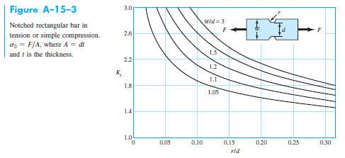
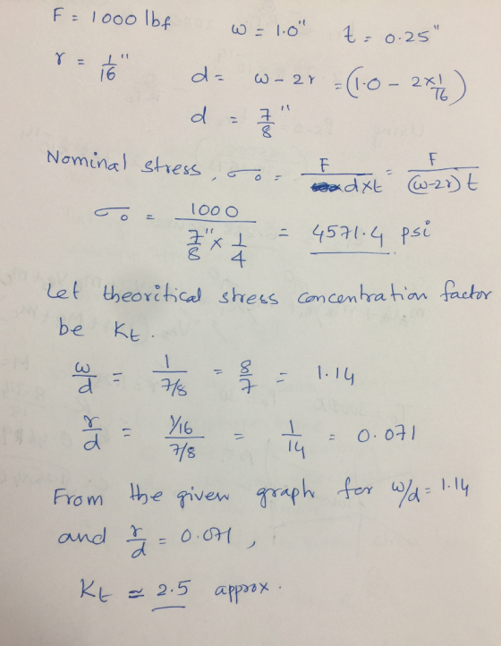
Determine the nominal stress and the theoretical or geometric stress concentration factor for a component geometry and loading described by Figure A-15-3.
a. F = 1,000 lbf
b. w = 1.0”
c. t = 0.25”
d. r = 1/16”
Homework Answers
Add Answer to:
Determine the nominal stress and the theoretical or geometric
stress concentration factor for a component geometry...
Question 1 Shaft AB is supported at B by a roller support and at A by a pin support as well as a spline that prevents rotation around x axis. The diameter of the shaft is D. At cross s...
 Question 1 Shaft AB is supported at B by a roller support and at A by a pin support as well as a spline that prevents rotation around x axis. The diameter of the shaft is D. At cross section A-A there is a relief groove where the minimum diameter is d. Two loads, F, and one torsion moment, T, are acted on the shaft. The material of the shaft is aluminum 7075, Sy = 495 MPa. Also known: L=630...
Question 2 The figure shows the free-body diagram of a connecting-link portion having stress concentration at...
 Question 2 The figure shows the free-body diagram of a connecting-link portion having stress concentration at three sections. The dimensions are r=0.25 in. d=0.40 in, h = 0.50 in, wl= 3.50 in, and w2 = 3.0 in. The forces F fluctuate between a tension of 15 kip and a compression of 46 kip. Neglect column action and find the least factor of safety if the material is cold-drawn AISI 1018 steel T- Section A-A I
find v belt drive design power select belt type determine shive size (belt speed 4000 ft/min)...
 find v belt drive
design power
select belt type
determine shive size (belt speed 4000 ft/min)
find shive size from power rating figure
find rated power
find estimated centre distance
find belt length (by selecting standard belt length)
calculate actual centre distance
find contact angle for small shieve
determine correct factors
calculate correct power per belt
no. of belt needed
V-Belt Designing Sample Problem . Given: A 4 cylinder diesel engine runs at 80 hp, 1800 rpm, to drive a...
find v belt drive
design power
select belt type
determine shive size (belt speed 4000 ft/min)
find shive size from power rating figure
find rated power
find estimated centre distance
find belt length (by selecting standard belt length)
calculate actual centre distance
find contact angle for small shieve
determine correct factors
calculate correct power per belt
no. of belt needed
V-Belt Designing Sample Problem . Given: A 4 cylinder diesel engine runs at 80 hp, 1800 rpm, to drive a...
 Question 1 Shaft AB is supported at B by a roller support and at A by a pin support as well as a spline that prevents rotation around x axis. The diameter of the shaft is D. At cross section A-A there is a relief groove where the minimum diameter is d. Two loads, F, and one torsion moment, T, are acted on the shaft. The material of the shaft is aluminum 7075, Sy = 495 MPa. Also known: L=630...
 Question 2 The figure shows the free-body diagram of a connecting-link portion having stress concentration at three sections. The dimensions are r=0.25 in. d=0.40 in, h = 0.50 in, wl= 3.50 in, and w2 = 3.0 in. The forces F fluctuate between a tension of 15 kip and a compression of 46 kip. Neglect column action and find the least factor of safety if the material is cold-drawn AISI 1018 steel T- Section A-A I
 find v belt drive
design power
select belt type
determine shive size (belt speed 4000 ft/min)
find shive size from power rating figure
find rated power
find estimated centre distance
find belt length (by selecting standard belt length)
calculate actual centre distance
find contact angle for small shieve
determine correct factors
calculate correct power per belt
no. of belt needed
V-Belt Designing Sample Problem . Given: A 4 cylinder diesel engine runs at 80 hp, 1800 rpm, to drive a...
find v belt drive
design power
select belt type
determine shive size (belt speed 4000 ft/min)
find shive size from power rating figure
find rated power
find estimated centre distance
find belt length (by selecting standard belt length)
calculate actual centre distance
find contact angle for small shieve
determine correct factors
calculate correct power per belt
no. of belt needed
V-Belt Designing Sample Problem . Given: A 4 cylinder diesel engine runs at 80 hp, 1800 rpm, to drive a...
Most questions answered within 3 hours.
-
Where is the error in this code sequence?
String s1 = "Hello";
String s2 = "ello";...
asked 11 months ago -
Financial data for Joel de Paris, Inc., for last year
follow:
Joel de Paris, Inc.
Balance...
asked 11 months ago -
Consider this reaction:
Al2(SO4)3 (aq)+ BaCl3
(aq) Al2Cl6 (aq)- +
3BaSO4(s) . What is the...
asked 11 months ago -
Suppose that Savneet is considering increasing her
recent random sample from 20 car rentals to 40...
asked 11 months ago -
Trucks arrive at an unloading terminal at an average rate of 120
per hour.
Trucks arrive...
asked 11 months ago -
Why are methanol and ethanol completely soluble in water while
octanol is not very little soluble....
asked 11 months ago -
A facilities manager at a university reads in a research report
that the mean amount of...
asked 11 months ago -
When the CuSO4 is rehydrated by adding water to the anhydrous
compound, is this an endothermic...
asked 11 months ago -
A ray of sunlight is passing from diamond into crown glass; the
angle of incidence is...
asked 11 months ago -
A block of mass 0.249 kg is placed on top of a light, vertical
spring of...
asked 11 months ago -
how do the kidneys compensate in the presences of acidosis
a) trigger hyperventilate
b) reserve acid...
asked 11 months ago -
Question 501 pts
The rental rate of capital to the firm increases. Which of the
following...
asked 11 months ago