Fro problem in this section, unless otherwise indicated, all allowable datapath components...
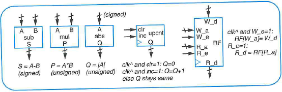
Fro problem in this section, unless otherwise indicated, all allowable datapath components are from Figure 5.21 and Figure 5.27, and controller design can end after deriving the FSM. Use the RTL design process for problem that state the need to “design” a system.
Using a timer, design a display system that reads the ASCII characters from a 64-word 8-bit register file RF and writes each word to a 2-row LED-based display having 32 characters per row, doing so 100 limes per second. The display has an 8-bit input A for the ASCII character to be displayed, a single-bit input row where 0 or 1 denotes the top or bottom row respectively, a 5-bit input col that indicates a column in the row, and an enable input en whose change from 0 to 1 causes the character to be displayed in the given row and column. The system should write RF[0| through RF[15] to row 0’s columns 0 to 15 respectively, and RF[16] to RF [31] to row 1
Figure 5.21 A basic datapath component library.

Figure 5.27 More datapath components for the library of Figure 5.21.
Step-by-Step Solution
Request Solution!
We need at least 10 more requests to produce the solution.
0 / 10 have requested this problem solution
The more requests, the faster the answer.
Most questions answered within 3 hours.
-
Calculating the space time for parallel reactions. m-Xylene is reacted over a ZSM-5 zeolit...
-
Determine Vo and ID for the networks of Fig. 2.160.FIG. 2.160
-
The truck travels along a circular road that has a radius of 50 m at a speed of 4 m/s. F...
-
A state legislature enacted a statute that required any motorcycle operator or passenger...
-
A 1024 × 1024 8-bit image with 5.3 bits/pixel entropy [computed from its histogram using E...
-
In Problem 3.3, we estimated the equationwhere we now report standard errors along with th...
-
In each of the following cases, deduce the nature of the light that is consistent with the...
-
Solve Example 20.5 such that the x, y, z axes move with curvilinear translation, Ω = 0 in...
-
In Fig. 6.43, if i = cos 4t and v = sin 4t, the element is:(a)a resistor(b) a capacitor(c)...
-
Sketch vo for each network of Fig. 2.181 for the input shown.FIG. 2.181
-
(Supplement B) Computing and Reporting Cash Flow Effectsof Sale of Plant and EquipmentDuri...
-
A 350-mL spherical flask contains 0.075 mol of an ideal gas at a temperature of 293 K. Wha...