1. Which of the resistors had the largest voltage drop? (R1 > R2 > R3) Also please explain what voltage drop is! Thanks!
Homework Answers

Add Answer to:
1. Which of the resistors had the largest voltage drop? (R1 >
R2 > R3) Also...
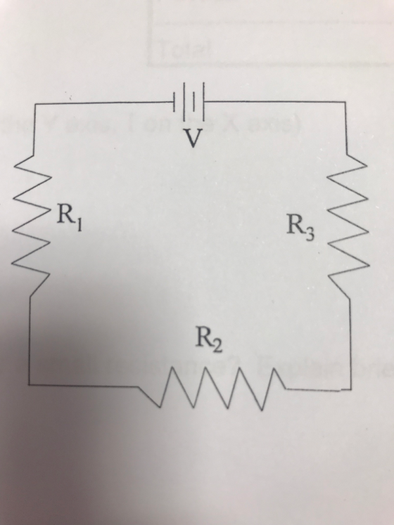
1. Three resistors are connected in a series-parallel circuit as shown. (R1 > R2 > R3)....
 1. Three resistors are connected in a series-parallel circuit as
shown. (R1 > R2 > R3). Which potential differences would be
greater, the voltage across R2 or the voltage across R3?
Explain.
2. Which of the resistors has the largest voltage drop across
it?
R2
1. Three resistors are connected in a series-parallel circuit as
shown. (R1 > R2 > R3). Which potential differences would be
greater, the voltage across R2 or the voltage across R3?
Explain.
2. Which of the resistors has the largest voltage drop across
it?
R2
Consider a circuit with four resistors in series. R1 R2 R3 R4 The battery has a...
 Consider a circuit with four resistors in series. R1 R2 R3 R4 The battery has a voltage of 12 V. The resistor values are R1-800 Ω. R2-600 Ω R3-500 Q . R4-500Q Complete the following table by noting the voltage drop across each listed resistor. Resistor (Q) Voltage Drop (V) R1 00Select R3500Select ] 00 Select ] R2 R4
2. Three resistors (R1, R2, and R3) are connected in parallel to a battery with a...
 2. Three resistors (R1, R2, and R3) are connected in parallel to a battery with a voltage of V. Assign values to R1 (2.0 Ω), R2 (4.0 Ω), and R3 (6.0 Ω) and voltage (9.0 V) a) Solve for the current through the battery. (3 pts) b) Solve for the current through R2. (3 pts)
R1 R3 R2 R4 W The circuit in the diagram contains one battery and four resistors,...
 R1 R3 R2 R4 W The circuit in the diagram contains one battery and four resistors, labeled 1 through 4. ?Which of the following is true about the way that the circuit elements are arranged Resistors 1 and 2 are in parallel while resistors 3 and 4 are in series Resistors 1 and 4 are in parallel while resistors 2 and 3 are in series Resistors 1 and 4 are in series, while resistors 2 and 3 are in parallel...
Consider the circuit shown in the figure with resistors R1= 4.0 Ω, R2= 3.0 Ω, R3=...
 Consider the circuit shown in the figure with resistors R1= 4.0
Ω, R2= 3.0 Ω, R3= 3.0 Ω, and batteries V1= 2.0 V, V2=1.5 V
respectively. What is the potential drop (voltage) across resistor
R3?
Consider the circuit shown in the figure with resistors R1= 4.0
Ω, R2= 3.0 Ω, R3= 3.0 Ω, and batteries V1= 2.0 V, V2=1.5 V
respectively. What is the potential drop (voltage) across resistor
R3?
Calculate the voltage and amperage across/through resistors R2 and R3 to detrrmine the power dissipated in...
 Calculate
the voltage and amperage across/through resistors R2 and R3 to
detrrmine the power dissipated in both resistors in terms of
Vs,R1,R2,R3
b) R2 R1 82Ω R3 330Ω Figure 1: Series/Parallel Circuit
Calculate
the voltage and amperage across/through resistors R2 and R3 to
detrrmine the power dissipated in both resistors in terms of
Vs,R1,R2,R3
b) R2 R1 82Ω R3 330Ω Figure 1: Series/Parallel Circuit
For the circuit of Figure 1, choose values for resistors R1, R2, and R3
 C.la For the circuit of Figure 1, choose values for resistors R1, R2, and R3(all resistances must be greater than one Kilo ohm). Given that the voltage source Vs1 = 8V and Vs2 = 10V determine the output voltage Vout. C.1b For the same resistor values Ri, R2, and Rs you chose in part C.la Given that the voltage source Vsi = 8V and Vs2 = 10V, use Figure 2(a) to determine the output voltage Vout/ and Figure 2(b) to determine the output voltage Vout2. Discussion:...
Please, write clearly! Will Upvote! Resistors R1 = 1 R2 = 2 R3 = 4 |...
Please, write clearly! Will Upvote! Resistors R1 = 1 R2 = 2 R3 = 4 | Battery = 12V(EMF) | I don't believe the battery has an internal resistance 1)Connect the resistors in series a)Find the equivalent resistance b)Find the total current in the circuit c)Calculate the terminal voltage of the battery 2)Connect the resistors in parallel a)Find the equivalent resistance b)Find the total current in the circuit c)Calculate the terminal voltage of the battery
for the lab sessions 3 , a group used the following resistors. R1= 40 , R2=...
for the lab sessions 3 , a group used the following resistors. R1= 40 , R2= 100, and R3= 150. and the DC applied was 15 volts. a) When the resistors were connected in series , what was the total current expected? b) Drow the circcuit. C)What was the voltage drop ecpected ar R2? d) When the same resistors were connected in parallel , what was the totla current? e) What was the voltage drop at each resistor? f) What...
Rc circuit R2 7) R3 Four resistors of values R1 = 2.0 Ω, R2 = 4.0...
 Rc circuit
R2 7) R3 Four resistors of values R1 = 2.0 Ω, R2 = 4.0 Ω, R3-3.00, and R4° 9.0 Ω are connected across an 8.0 VDC source as shown in the above figure, what is the power dissipated in R2, the 4.00 resistor? A) 4.0 W B) 16. W C)9.0 W D) 7.1 W E) 1.0 W 8) Also calculate the voltage across R a) 1 V b) 2 V c) 3 V d) 4 V
Rc circuit
R2 7) R3 Four resistors of values R1 = 2.0 Ω, R2 = 4.0 Ω, R3-3.00, and R4° 9.0 Ω are connected across an 8.0 VDC source as shown in the above figure, what is the power dissipated in R2, the 4.00 resistor? A) 4.0 W B) 16. W C)9.0 W D) 7.1 W E) 1.0 W 8) Also calculate the voltage across R a) 1 V b) 2 V c) 3 V d) 4 V
 1. Three resistors are connected in a series-parallel circuit as
shown. (R1 > R2 > R3). Which potential differences would be
greater, the voltage across R2 or the voltage across R3?
Explain.
2. Which of the resistors has the largest voltage drop across
it?
R2
1. Three resistors are connected in a series-parallel circuit as
shown. (R1 > R2 > R3). Which potential differences would be
greater, the voltage across R2 or the voltage across R3?
Explain.
2. Which of the resistors has the largest voltage drop across
it?
R2
 Consider a circuit with four resistors in series. R1 R2 R3 R4 The battery has a voltage of 12 V. The resistor values are R1-800 Ω. R2-600 Ω R3-500 Q . R4-500Q Complete the following table by noting the voltage drop across each listed resistor. Resistor (Q) Voltage Drop (V) R1 00Select R3500Select ] 00 Select ] R2 R4
 2. Three resistors (R1, R2, and R3) are connected in parallel to a battery with a voltage of V. Assign values to R1 (2.0 Ω), R2 (4.0 Ω), and R3 (6.0 Ω) and voltage (9.0 V) a) Solve for the current through the battery. (3 pts) b) Solve for the current through R2. (3 pts)
 R1 R3 R2 R4 W The circuit in the diagram contains one battery and four resistors, labeled 1 through 4. ?Which of the following is true about the way that the circuit elements are arranged Resistors 1 and 2 are in parallel while resistors 3 and 4 are in series Resistors 1 and 4 are in parallel while resistors 2 and 3 are in series Resistors 1 and 4 are in series, while resistors 2 and 3 are in parallel...
 Consider the circuit shown in the figure with resistors R1= 4.0
Ω, R2= 3.0 Ω, R3= 3.0 Ω, and batteries V1= 2.0 V, V2=1.5 V
respectively. What is the potential drop (voltage) across resistor
R3?
Consider the circuit shown in the figure with resistors R1= 4.0
Ω, R2= 3.0 Ω, R3= 3.0 Ω, and batteries V1= 2.0 V, V2=1.5 V
respectively. What is the potential drop (voltage) across resistor
R3?
 Calculate
the voltage and amperage across/through resistors R2 and R3 to
detrrmine the power dissipated in both resistors in terms of
Vs,R1,R2,R3
b) R2 R1 82Ω R3 330Ω Figure 1: Series/Parallel Circuit
Calculate
the voltage and amperage across/through resistors R2 and R3 to
detrrmine the power dissipated in both resistors in terms of
Vs,R1,R2,R3
b) R2 R1 82Ω R3 330Ω Figure 1: Series/Parallel Circuit
 C.la For the circuit of Figure 1, choose values for resistors R1, R2, and R3(all resistances must be greater than one Kilo ohm). Given that the voltage source Vs1 = 8V and Vs2 = 10V determine the output voltage Vout. C.1b For the same resistor values Ri, R2, and Rs you chose in part C.la Given that the voltage source Vsi = 8V and Vs2 = 10V, use Figure 2(a) to determine the output voltage Vout/ and Figure 2(b) to determine the output voltage Vout2. Discussion:...
 Rc circuit
R2 7) R3 Four resistors of values R1 = 2.0 Ω, R2 = 4.0 Ω, R3-3.00, and R4° 9.0 Ω are connected across an 8.0 VDC source as shown in the above figure, what is the power dissipated in R2, the 4.00 resistor? A) 4.0 W B) 16. W C)9.0 W D) 7.1 W E) 1.0 W 8) Also calculate the voltage across R a) 1 V b) 2 V c) 3 V d) 4 V
Rc circuit
R2 7) R3 Four resistors of values R1 = 2.0 Ω, R2 = 4.0 Ω, R3-3.00, and R4° 9.0 Ω are connected across an 8.0 VDC source as shown in the above figure, what is the power dissipated in R2, the 4.00 resistor? A) 4.0 W B) 16. W C)9.0 W D) 7.1 W E) 1.0 W 8) Also calculate the voltage across R a) 1 V b) 2 V c) 3 V d) 4 V
Most questions answered within 3 hours.
-
Where is the error in this code sequence?
String s1 = "Hello";
String s2 = "ello";...
asked 11 months ago -
Financial data for Joel de Paris, Inc., for last year
follow:
Joel de Paris, Inc.
Balance...
asked 11 months ago -
Consider this reaction:
Al2(SO4)3 (aq)+ BaCl3
(aq) Al2Cl6 (aq)- +
3BaSO4(s) . What is the...
asked 11 months ago -
Suppose that Savneet is considering increasing her
recent random sample from 20 car rentals to 40...
asked 11 months ago -
Trucks arrive at an unloading terminal at an average rate of 120
per hour.
Trucks arrive...
asked 11 months ago -
Why are methanol and ethanol completely soluble in water while
octanol is not very little soluble....
asked 11 months ago -
A facilities manager at a university reads in a research report
that the mean amount of...
asked 11 months ago -
When the CuSO4 is rehydrated by adding water to the anhydrous
compound, is this an endothermic...
asked 11 months ago -
A ray of sunlight is passing from diamond into crown glass; the
angle of incidence is...
asked 11 months ago -
A block of mass 0.249 kg is placed on top of a light, vertical
spring of...
asked 11 months ago -
how do the kidneys compensate in the presences of acidosis
a) trigger hyperventilate
b) reserve acid...
asked 11 months ago -
Question 501 pts
The rental rate of capital to the firm increases. Which of the
following...
asked 11 months ago