radio frequency engineering
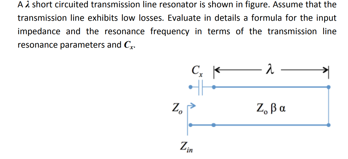
A λ short circuited transmission line resonator is shown in figure. Assume that the transmission line exhibits low losses. Evaluate in details a formula for the input impedance and the resonance frequency in terms of the transmission line resonance parameters and Cx.
Homework Answers
Request Answer!
We need at least 10 more requests to produce the answer.
0 / 10 have requested this problem solution
The more requests, the faster the answer.
[50] You have a load with impedance (10+j10)? at the design frequency, f-100 MHz, that you...
 [50] You have a load with impedance (10+j10)? at the design frequency, f-100 MHz, that you want to match to a 50? transmission line (v,-3.108m/s). Using Smith charts, construct matching networks using the following elements: (a) a short-circuited parallel stub, (b) an open- circuited parallel stub, (c) a short-circuited series stub, (d) an open-circuited series stub, (e) a quarter-wave transformer. Assume ideal components. Specify the length of each transmission line in meters. ·
In a radio frequency circuit, a resistance of 1752 Ω serves as a load at the...
In a radio frequency circuit, a resistance of 1752 Ω serves as a load at the end of a 50 Ω transmission line. We wish to connect an inductor, L, in series to the input of the line so that a source with an output impedance of 50 Ω does not see reflections. No need to know the frequency to solve the problem (a) Determine the minimum length of the transmission line in terms of wavelengths. (b) Determine the value...
answer number 3 and 4 Problem 7. Transmission Lines The figure below shows a transmission line with a characteristic impedance Z,-50 Ω, connected to a single frequency generator with an internal i...
 answer number 3 and 4
Problem 7. Transmission Lines The figure below shows a transmission line with a characteristic impedance Z,-50 Ω, connected to a single frequency generator with an internal impedance R,-50 C (not shown), and terminated in a purely resistive load RL 50 2. At the frequency of the generator, the wavelength of the transmission line is λ = 2 m. At a distance dl-1.25 m away from the load, a shorted stub is connected via a tee....
answer number 3 and 4
Problem 7. Transmission Lines The figure below shows a transmission line with a characteristic impedance Z,-50 Ω, connected to a single frequency generator with an internal impedance R,-50 C (not shown), and terminated in a purely resistive load RL 50 2. At the frequency of the generator, the wavelength of the transmission line is λ = 2 m. At a distance dl-1.25 m away from the load, a shorted stub is connected via a tee....
2. Three transmission lines are connected as shown below. Note that 3) is short- circuited and...
 2. Three transmission lines are connected as shown below. Note that 3) is short- circuited and it is connected in series to the tandem of transmission lines I and 2. Calculate Zin (input impedance of line) ap the input port (sinusoidal steady state mode operating at the frequency of 100 MHz)、The velocity of propagation on all lines are identical. Also, what is the value of the equivalent circuit element for Zin? 100 Zol= 100 Ω di-A Zin as-75 Ω
You have an antenna with an input impedance of Z (140 -j35)2 at f 120 MHz....
 You have an antenna with an input impedance of Z (140 -j35)2 at f 120 MHz. You would like to match this load to a 70Ω transmission line using a single stub tuner (vp-2.2x10⁸ m/s). Using the Smith chart, determine the distance d away from the load and the length l of a short-circuited parallel stub to accomplish the matching goal at the design frequency. Estimate the reduction in radiated power if the operating frequency is changed to f 125...
Problem 3-15. Steady-State Conditions on a Transmission Line ine Che Chap. 3 3-11. A certain telephone...
 Problem 3-15.
Steady-State Conditions on a Transmission Line ine Che Chap. 3 3-11. A certain telephone cable has the following electrical characteristics: R = 40 /mi L = 1.1 mH/mi G = negligible C = 0.062 F/mi Loading coils are added which provide an additional inductance of 30 m / well as an additional resistance of 8 l/mi. Obtain the attenuation constan phase velocities at frequencies of 300 Hz and 3300 Hz. If the coil spacing is 1/6 at a...
Problem 3-15.
Steady-State Conditions on a Transmission Line ine Che Chap. 3 3-11. A certain telephone cable has the following electrical characteristics: R = 40 /mi L = 1.1 mH/mi G = negligible C = 0.062 F/mi Loading coils are added which provide an additional inductance of 30 m / well as an additional resistance of 8 l/mi. Obtain the attenuation constan phase velocities at frequencies of 300 Hz and 3300 Hz. If the coil spacing is 1/6 at a...
elementR,-150 Ω is inserted in-between two lossless TEM A series lumped resisive in the figure below....
 elementR,-150 Ω is inserted in-between two lossless TEM A series lumped resisive in the figure below. The characteristic impedance of the first 2. ransm ol 100 Ω and the phase velocity is the speed of light (up transmission line (Tx-Line 1) SCctie impedance of the second transmission line (Tx-Line 2) section c = 3 x 10⁸ m/s). The character ond transmission line is terminated to the right so that there is no ission line sections as shown C3 x 10...
Problem 2 (10 points) In the amplifier shown in Fig. 2(a), assume Fig. 2(b) that I4 is ideal. Do not ignore the ro of t...
 Problem 2 (10 points) In the amplifier shown in Fig. 2(a), assume Fig. 2(b) that I4 is ideal. Do not ignore the ro of the transistors for this problem, but you can assume that Ri is much smaller than any transistor o I1 and I2 ideal current sources. Also, assume in are (a) Find the small signal differential gain out/vdm of the Fig. 2(a) amplifier in terms of the appropriate small-signal parameters. Then express your answer in terms of appropriate...
Laboratory 1: operation amplifier characteristics A. Objectives: 1. To study the basic characteri...
 thanks
Laboratory 1: operation amplifier characteristics A. Objectives: 1. To study the basic characteristics of an operational amplifier 2. To study the bias circuit of an operational amplifier B. Apparatus: 1. DC Power supply 2. Experimental board and corresponding components 3. Electronic calculator (prepared by students) 4. Digital camera (prepared by students for photo taking of the experimental results) 5. Laptop computer with the software PicoScope 6 and Microsoft Word installed. 6. PicoScope PC Oscilloscope and its accessories. 7. Multimeter...
thanks
Laboratory 1: operation amplifier characteristics A. Objectives: 1. To study the basic characteristics of an operational amplifier 2. To study the bias circuit of an operational amplifier B. Apparatus: 1. DC Power supply 2. Experimental board and corresponding components 3. Electronic calculator (prepared by students) 4. Digital camera (prepared by students for photo taking of the experimental results) 5. Laptop computer with the software PicoScope 6 and Microsoft Word installed. 6. PicoScope PC Oscilloscope and its accessories. 7. Multimeter...
Paper Design only!! output matehing In this assignment you are to design and implement in ADS two networks: an LC matchi...
 Paper Design only!!
output matehing In this assignment you are to design and implement in ADS two networks: an LC matching network and a microstrip short-circuit stub matching network. These matching networks between a 50 termination and an RF transistor with output impedance ZouT 25 + j50 Thus we require the matching networks transform a 50 2 termination to an impedance of Z, 25-50 at an operating frequency of f 1 GHz, intended to obtain a conjugate match, for maximum...
Paper Design only!!
output matehing In this assignment you are to design and implement in ADS two networks: an LC matching network and a microstrip short-circuit stub matching network. These matching networks between a 50 termination and an RF transistor with output impedance ZouT 25 + j50 Thus we require the matching networks transform a 50 2 termination to an impedance of Z, 25-50 at an operating frequency of f 1 GHz, intended to obtain a conjugate match, for maximum...
 [50] You have a load with impedance (10+j10)? at the design frequency, f-100 MHz, that you want to match to a 50? transmission line (v,-3.108m/s). Using Smith charts, construct matching networks using the following elements: (a) a short-circuited parallel stub, (b) an open- circuited parallel stub, (c) a short-circuited series stub, (d) an open-circuited series stub, (e) a quarter-wave transformer. Assume ideal components. Specify the length of each transmission line in meters. ·
 answer number 3 and 4
Problem 7. Transmission Lines The figure below shows a transmission line with a characteristic impedance Z,-50 Ω, connected to a single frequency generator with an internal impedance R,-50 C (not shown), and terminated in a purely resistive load RL 50 2. At the frequency of the generator, the wavelength of the transmission line is λ = 2 m. At a distance dl-1.25 m away from the load, a shorted stub is connected via a tee....
answer number 3 and 4
Problem 7. Transmission Lines The figure below shows a transmission line with a characteristic impedance Z,-50 Ω, connected to a single frequency generator with an internal impedance R,-50 C (not shown), and terminated in a purely resistive load RL 50 2. At the frequency of the generator, the wavelength of the transmission line is λ = 2 m. At a distance dl-1.25 m away from the load, a shorted stub is connected via a tee....
 2. Three transmission lines are connected as shown below. Note that 3) is short- circuited and it is connected in series to the tandem of transmission lines I and 2. Calculate Zin (input impedance of line) ap the input port (sinusoidal steady state mode operating at the frequency of 100 MHz)、The velocity of propagation on all lines are identical. Also, what is the value of the equivalent circuit element for Zin? 100 Zol= 100 Ω di-A Zin as-75 Ω
 You have an antenna with an input impedance of Z (140 -j35)2 at f 120 MHz. You would like to match this load to a 70Ω transmission line using a single stub tuner (vp-2.2x10⁸ m/s). Using the Smith chart, determine the distance d away from the load and the length l of a short-circuited parallel stub to accomplish the matching goal at the design frequency. Estimate the reduction in radiated power if the operating frequency is changed to f 125...
 Problem 3-15.
Steady-State Conditions on a Transmission Line ine Che Chap. 3 3-11. A certain telephone cable has the following electrical characteristics: R = 40 /mi L = 1.1 mH/mi G = negligible C = 0.062 F/mi Loading coils are added which provide an additional inductance of 30 m / well as an additional resistance of 8 l/mi. Obtain the attenuation constan phase velocities at frequencies of 300 Hz and 3300 Hz. If the coil spacing is 1/6 at a...
Problem 3-15.
Steady-State Conditions on a Transmission Line ine Che Chap. 3 3-11. A certain telephone cable has the following electrical characteristics: R = 40 /mi L = 1.1 mH/mi G = negligible C = 0.062 F/mi Loading coils are added which provide an additional inductance of 30 m / well as an additional resistance of 8 l/mi. Obtain the attenuation constan phase velocities at frequencies of 300 Hz and 3300 Hz. If the coil spacing is 1/6 at a...
 elementR,-150 Ω is inserted in-between two lossless TEM A series lumped resisive in the figure below. The characteristic impedance of the first 2. ransm ol 100 Ω and the phase velocity is the speed of light (up transmission line (Tx-Line 1) SCctie impedance of the second transmission line (Tx-Line 2) section c = 3 x 10⁸ m/s). The character ond transmission line is terminated to the right so that there is no ission line sections as shown C3 x 10...
 Problem 2 (10 points) In the amplifier shown in Fig. 2(a), assume Fig. 2(b) that I4 is ideal. Do not ignore the ro of the transistors for this problem, but you can assume that Ri is much smaller than any transistor o I1 and I2 ideal current sources. Also, assume in are (a) Find the small signal differential gain out/vdm of the Fig. 2(a) amplifier in terms of the appropriate small-signal parameters. Then express your answer in terms of appropriate...
 thanks
Laboratory 1: operation amplifier characteristics A. Objectives: 1. To study the basic characteristics of an operational amplifier 2. To study the bias circuit of an operational amplifier B. Apparatus: 1. DC Power supply 2. Experimental board and corresponding components 3. Electronic calculator (prepared by students) 4. Digital camera (prepared by students for photo taking of the experimental results) 5. Laptop computer with the software PicoScope 6 and Microsoft Word installed. 6. PicoScope PC Oscilloscope and its accessories. 7. Multimeter...
thanks
Laboratory 1: operation amplifier characteristics A. Objectives: 1. To study the basic characteristics of an operational amplifier 2. To study the bias circuit of an operational amplifier B. Apparatus: 1. DC Power supply 2. Experimental board and corresponding components 3. Electronic calculator (prepared by students) 4. Digital camera (prepared by students for photo taking of the experimental results) 5. Laptop computer with the software PicoScope 6 and Microsoft Word installed. 6. PicoScope PC Oscilloscope and its accessories. 7. Multimeter...
 Paper Design only!!
output matehing In this assignment you are to design and implement in ADS two networks: an LC matching network and a microstrip short-circuit stub matching network. These matching networks between a 50 termination and an RF transistor with output impedance ZouT 25 + j50 Thus we require the matching networks transform a 50 2 termination to an impedance of Z, 25-50 at an operating frequency of f 1 GHz, intended to obtain a conjugate match, for maximum...
Paper Design only!!
output matehing In this assignment you are to design and implement in ADS two networks: an LC matching network and a microstrip short-circuit stub matching network. These matching networks between a 50 termination and an RF transistor with output impedance ZouT 25 + j50 Thus we require the matching networks transform a 50 2 termination to an impedance of Z, 25-50 at an operating frequency of f 1 GHz, intended to obtain a conjugate match, for maximum...
Most questions answered within 3 hours.
-
Where is the error in this code sequence?
String s1 = "Hello";
String s2 = "ello";...
asked 10 months ago -
Financial data for Joel de Paris, Inc., for last year
follow:
Joel de Paris, Inc.
Balance...
asked 10 months ago -
Consider this reaction:
Al2(SO4)3 (aq)+ BaCl3
(aq) Al2Cl6 (aq)- +
3BaSO4(s) . What is the...
asked 10 months ago -
Suppose that Savneet is considering increasing her
recent random sample from 20 car rentals to 40...
asked 10 months ago -
Trucks arrive at an unloading terminal at an average rate of 120
per hour.
Trucks arrive...
asked 10 months ago -
Why are methanol and ethanol completely soluble in water while
octanol is not very little soluble....
asked 10 months ago -
A facilities manager at a university reads in a research report
that the mean amount of...
asked 10 months ago -
When the CuSO4 is rehydrated by adding water to the anhydrous
compound, is this an endothermic...
asked 10 months ago -
A ray of sunlight is passing from diamond into crown glass; the
angle of incidence is...
asked 10 months ago -
A block of mass 0.249 kg is placed on top of a light, vertical
spring of...
asked 10 months ago -
how do the kidneys compensate in the presences of acidosis
a) trigger hyperventilate
b) reserve acid...
asked 10 months ago -
Question 501 pts
The rental rate of capital to the firm increases. Which of the
following...
asked 10 months ago