
Homework Answers


Add Answer to:
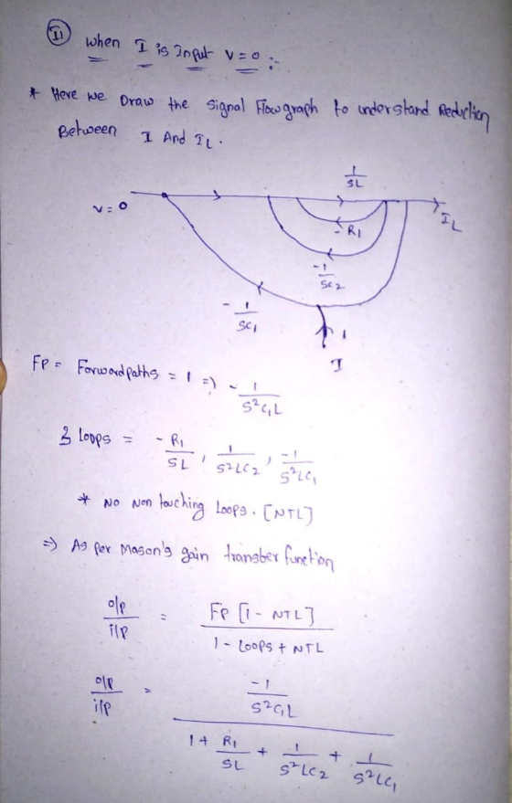
The block diagram of this system showing the two inputs I and V, one output i,,...
c(s), A system has a block diagram as shown. The input is R(s) and the output...
 c(s), A system has a block diagram as shown. The input is R(s) and the output is C(s). a) Using only the block diagram reduction method", find the transfer function of the system. b) Determine the characteristic function and the order of the system. c) Find the characteristic roots of the system. d) Find the natural frequency of the system. e) Find the damped natural frequency of the system. 8 * NOTE: All stages of block diagram reduction must be...
Design a full adder from scratch. (a) Identify inputs and outputs (b) Draw a block diagram...
Design a full adder from scratch. (a) Identify inputs and outputs (b) Draw a block diagram (c) Show the truth tables (d) Determine a minimized Boolean expression for the carry output (e) Draw an AND-OR circuit for the carry output (f) Derive a minimized product-of-sums expression for the carry output of the system
Matlab Homework #4: Matlab Linear Systems Simulation 1.) Obtain the differential equation for the...
 Matlab Homework #4: Matlab Linear Systems Simulation 1.) Obtain the differential equation for the mechanical system shown below bi FLR) orce CN) voltege ) 2.) Obtain the differential equation for the electrical system shown below shown below OAF 3.) Find the transfer functions corresponding to the differential equations found in questions I and 2 the 4) Let the input force applied to the block of the mechanical system be zero U)-のThe initial conditions are y(0) = 10 cm and dy(0)d-0....
Draw a block diagram of the system shown below Figure P6.36 is the circuit diagram of...
 Draw a block diagram of the system shown below
Figure P6.36 is the circuit diagram of a speed-control system in which the dc motor voltage ua is supplied by a generator driven by an engine. This system has been used on locomotives whose diesel engine operates most efficiently at one speed. The efficiency of the electric motor is not as sensitive to speed and thus can be used to drive the locomotive at various speeds. The motor voltage va is...
Draw a block diagram of the system shown below
Figure P6.36 is the circuit diagram of a speed-control system in which the dc motor voltage ua is supplied by a generator driven by an engine. This system has been used on locomotives whose diesel engine operates most efficiently at one speed. The efficiency of the electric motor is not as sensitive to speed and thus can be used to drive the locomotive at various speeds. The motor voltage va is...
Find the transfer function Given below is a block diagram of a load frequency control system...
 Find the transfer function
Given below is a block diagram of a load frequency control system with two inputs, the speed changer AP.(t) and load disturbance Apa(t), and the output is the system frequency error Af(t). 20 APD APC 0.25 +1 2.1s +1 2.1s2 + 7.3s +1 10s +1
Find the transfer function
Given below is a block diagram of a load frequency control system with two inputs, the speed changer AP.(t) and load disturbance Apa(t), and the output is the system frequency error Af(t). 20 APD APC 0.25 +1 2.1s +1 2.1s2 + 7.3s +1 10s +1
4. Given the block diagram as shown, and D are inputs and G, G2, and H,...
 4. Given the block diagram as shown, and D are inputs and G, G2, and H, are transfer functions. a) Using only the block diagram reduction R+ G method*, find the transfer function C/R in terms of G, G, and Hz. H b) Using only the block diagram reduction method*, find the transfer function E/D in terms of G, G2, and Hz. c) Using either the block diagram reduction method* or the equation method, find the transfer function E/R in...
yce) Figure 1: Time-domain block diagram, with input u(t) and output y(t). For the block diagram...
 yce) Figure 1: Time-domain block diagram, with input u(t) and output y(t). For the block diagram shown in Figure find the system transfer function Y (s)/U(s).
A neural network has two inputs and one output, and has five neurons in the single...
A neural network has two inputs and one output, and has five neurons in the single hidden layer. Draw a diagram of the network showing all the connections, and label the layers.
R E UA Given the block diagram as shown, R and D are inputs and G,...
 R E UA Given the block diagram as shown, R and D are inputs and G, G, and H, are transfer functions. a) Using only the block diagram reduction G G method", find the transfer function C/R in terms of G, G, and H. H, b) Using only the block diagram reduction method*, find the transfer function E/D in terms of G, G, and Hz. c) Using either the block diagram reduction method* or the equation method, find the transfer...
Problem 3: (30 Consider a block diagram which represents the satellite control system with a cont...
 Problem 3: (30 Consider a block diagram which represents the satellite control system with a controller Ge(s) (a) Assuming no initial conditions, find the output response y(t) when the impulse input is applied to the system, where Gc(s) is a proportional gain K. (10) (b) Design a lead-compensator Ge(s) for which the complex pole of the closed-loop system has 0.5 of damping ratio () and 2 rad/s of undamped natural frequency (on) (The zero of a lead-compensator is given as...
 c(s), A system has a block diagram as shown. The input is R(s) and the output is C(s). a) Using only the block diagram reduction method", find the transfer function of the system. b) Determine the characteristic function and the order of the system. c) Find the characteristic roots of the system. d) Find the natural frequency of the system. e) Find the damped natural frequency of the system. 8 * NOTE: All stages of block diagram reduction must be...
 Matlab Homework #4: Matlab Linear Systems Simulation 1.) Obtain the differential equation for the mechanical system shown below bi FLR) orce CN) voltege ) 2.) Obtain the differential equation for the electrical system shown below shown below OAF 3.) Find the transfer functions corresponding to the differential equations found in questions I and 2 the 4) Let the input force applied to the block of the mechanical system be zero U)-のThe initial conditions are y(0) = 10 cm and dy(0)d-0....
 Draw a block diagram of the system shown below
Figure P6.36 is the circuit diagram of a speed-control system in which the dc motor voltage ua is supplied by a generator driven by an engine. This system has been used on locomotives whose diesel engine operates most efficiently at one speed. The efficiency of the electric motor is not as sensitive to speed and thus can be used to drive the locomotive at various speeds. The motor voltage va is...
Draw a block diagram of the system shown below
Figure P6.36 is the circuit diagram of a speed-control system in which the dc motor voltage ua is supplied by a generator driven by an engine. This system has been used on locomotives whose diesel engine operates most efficiently at one speed. The efficiency of the electric motor is not as sensitive to speed and thus can be used to drive the locomotive at various speeds. The motor voltage va is...
 Find the transfer function
Given below is a block diagram of a load frequency control system with two inputs, the speed changer AP.(t) and load disturbance Apa(t), and the output is the system frequency error Af(t). 20 APD APC 0.25 +1 2.1s +1 2.1s2 + 7.3s +1 10s +1
Find the transfer function
Given below is a block diagram of a load frequency control system with two inputs, the speed changer AP.(t) and load disturbance Apa(t), and the output is the system frequency error Af(t). 20 APD APC 0.25 +1 2.1s +1 2.1s2 + 7.3s +1 10s +1
 4. Given the block diagram as shown, and D are inputs and G, G2, and H, are transfer functions. a) Using only the block diagram reduction R+ G method*, find the transfer function C/R in terms of G, G, and Hz. H b) Using only the block diagram reduction method*, find the transfer function E/D in terms of G, G2, and Hz. c) Using either the block diagram reduction method* or the equation method, find the transfer function E/R in...
 yce) Figure 1: Time-domain block diagram, with input u(t) and output y(t). For the block diagram shown in Figure find the system transfer function Y (s)/U(s).
 R E UA Given the block diagram as shown, R and D are inputs and G, G, and H, are transfer functions. a) Using only the block diagram reduction G G method", find the transfer function C/R in terms of G, G, and H. H, b) Using only the block diagram reduction method*, find the transfer function E/D in terms of G, G, and Hz. c) Using either the block diagram reduction method* or the equation method, find the transfer...
 Problem 3: (30 Consider a block diagram which represents the satellite control system with a controller Ge(s) (a) Assuming no initial conditions, find the output response y(t) when the impulse input is applied to the system, where Gc(s) is a proportional gain K. (10) (b) Design a lead-compensator Ge(s) for which the complex pole of the closed-loop system has 0.5 of damping ratio () and 2 rad/s of undamped natural frequency (on) (The zero of a lead-compensator is given as...
Most questions answered within 3 hours.
-
Where is the error in this code sequence?
String s1 = "Hello";
String s2 = "ello";...
asked 11 months ago -
Financial data for Joel de Paris, Inc., for last year
follow:
Joel de Paris, Inc.
Balance...
asked 11 months ago -
Consider this reaction:
Al2(SO4)3 (aq)+ BaCl3
(aq) Al2Cl6 (aq)- +
3BaSO4(s) . What is the...
asked 11 months ago -
Suppose that Savneet is considering increasing her
recent random sample from 20 car rentals to 40...
asked 11 months ago -
Trucks arrive at an unloading terminal at an average rate of 120
per hour.
Trucks arrive...
asked 11 months ago -
Why are methanol and ethanol completely soluble in water while
octanol is not very little soluble....
asked 11 months ago -
A facilities manager at a university reads in a research report
that the mean amount of...
asked 11 months ago -
When the CuSO4 is rehydrated by adding water to the anhydrous
compound, is this an endothermic...
asked 11 months ago -
A ray of sunlight is passing from diamond into crown glass; the
angle of incidence is...
asked 11 months ago -
A block of mass 0.249 kg is placed on top of a light, vertical
spring of...
asked 11 months ago -
how do the kidneys compensate in the presences of acidosis
a) trigger hyperventilate
b) reserve acid...
asked 11 months ago -
Question 501 pts
The rental rate of capital to the firm increases. Which of the
following...
asked 11 months ago