![6) [18 marks] You have been asked to implement a circuit for a graphics application. This circuit consists of three inputs (P](http://img.homeworklib.com/questions/e44c65a0-9554-11ea-85b5-0f2a215d2149.png?x-oss-process=image/resize,w_560)
Homework Answers
Answer :


Add Answer to:
6) [18 marks] You have been asked to implement a circuit for a graphics application. This...
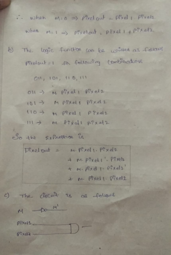
Q6. a) Write the output expression for the circuit shown in the figure. b) Develop truth...
 Q6. a) Write the output expression for the circuit shown in the figure. b) Develop truth table for the circuit. (1 Mark) (4 Marks) A B C 13 X D Fig.2 07 [5] a) Minimize the following logic function using K-Map. b) Implement the minimized expression using basic gates. (3 Marks) (2 Marks) F(A,B,C,D) = (0,2,5,7,8,10,13,15) Q8 a) Write the output expression of the logic circuit shown in the figure. b) Minimize the expression using Boolean laws and theorems. C)...
1.) You have been handed a state diagram that you have been asked to implement the design for. (Unused states: extra state encodings can be treated as "don't care" values and are use...
 1.) You have been handed a state diagram that you have been asked to implement the design for. (Unused states: extra state encodings can be treated as "don't care" values and are used to simplify the combinational logic.) Next State State Name 01 State Name 020+1) 010+1) Oo+1) a. Implement the design using T flip-flops, JK flip-flops, and SR flip-flops b. Determine the Boolean expression for the inputs of the different types of flip-flops and the output.
1.) You have...
1.) You have been handed a state diagram that you have been asked to implement the design for. (Unused states: extra state encodings can be treated as "don't care" values and are used to simplify the combinational logic.) Next State State Name 01 State Name 020+1) 010+1) Oo+1) a. Implement the design using T flip-flops, JK flip-flops, and SR flip-flops b. Determine the Boolean expression for the inputs of the different types of flip-flops and the output.
1.) You have...
Please show step by step, complete solution and explain if possible. Thank you so much. 3....
 Please show step by step, complete solution and explain if
possible. Thank you so much.
3. Six-Sided Die Display Circuit In this problem, you will design a logic circuit to display the six faces of a die using 7 LEDs. For example, the value 5 is shown on the display below. Your circuit takes three bits XYZ as input and outputs the patterns shown in the table below, by lighting up the correspondind LEDs. For example, for the value 5,...
Please show step by step, complete solution and explain if
possible. Thank you so much.
3. Six-Sided Die Display Circuit In this problem, you will design a logic circuit to display the six faces of a die using 7 LEDs. For example, the value 5 is shown on the display below. Your circuit takes three bits XYZ as input and outputs the patterns shown in the table below, by lighting up the correspondind LEDs. For example, for the value 5,...
You will build a seven-segment display decoder, shown in Figure 3. The circuit has four input...
You will build a seven-segment display decoder, shown in Figure 3. The circuit has four input bits, D3:0 (representing a hexadecimal number between 0 and F), and produces seven output bits, Sa:g, that drive the seven segments to display the number. The 7-segment display we will use in this lab is a common cathode type, a segment of the display turns on when it is 1. The other type of 7-segment display is common anode, for which a segment turns...
A combination circuit is specified by the following Boolean functions listed below. h(a, b, c) = b,c' + a'c Implement the circuit with a 3x8 decoder. Provide truth table and drawing the l...
 A combination circuit is specified by the following Boolean functions listed below. h(a, b, c) = b,c' + a'c Implement the circuit with a 3x8 decoder. Provide truth table and drawing the logic/circuit diagram. Use the block diagram for the decoder provided in Figure A4 in supplements. Please label the inputs and outputs clearly. Note: use single 3x8 decoder Question 2 (15 points] A priority encoder is an encoder circuit that includes the Truth Table of a priority function. The...
You have been asked to implement a new blood glucose monitoring software application. Provide a communication...
You have been asked to implement a new blood glucose monitoring software application. Provide a communication plan that includes who, what, when, and how.
DESIGN SECTION Before the experiment, you are going to design a circuit which has 4 inputs...
DESIGN SECTION Before the experiment, you are going to design a circuit which has 4 inputs w, x, y, z and an output F. If 4-bits input value is “odd number which is higher than 4”, or “3-bits highest even number” or “4-bits highest even number”, the output function F will be equal to 1. Otherwise F=0. Each students have to design the circuit and have to do following steps own by own. You are going to; a) Fill the...
Hi, please help and write clearly. Thanks. uestion 2 (30 marks (a) A memory system of...
 Hi, please help and write clearly. Thanks.
uestion 2 (30 marks (a) A memory system of 64 bit is arranged into 4096 rows and 128 columns Calculatee (i)The data length in bytes (ii)The number of bits stored in the memory (iii)The number of row and column addresse:s [2 marks] [4 marks] [4 marks] (b)A Programmable Read Only Memory (PROM) based Programmable logic device (PLD) has the following characteristics When C-0, output is A. When C-1, output is B (i)Determine the...
Hi, please help and write clearly. Thanks.
uestion 2 (30 marks (a) A memory system of 64 bit is arranged into 4096 rows and 128 columns Calculatee (i)The data length in bytes (ii)The number of bits stored in the memory (iii)The number of row and column addresse:s [2 marks] [4 marks] [4 marks] (b)A Programmable Read Only Memory (PROM) based Programmable logic device (PLD) has the following characteristics When C-0, output is A. When C-1, output is B (i)Determine the...
You have been asked to develop an application that accepts a sentence from the user and...
You have been asked to develop an application that accepts a sentence from the user and calculates and displays the number of vowels, consonants and spaces in that sentence. The application should run once and then ask the user if they would like to run it again. NB. The only acceptable characters are space, vowels and consonants. You are not expected to code for this. It is relevant only when testing the application. Your application should be developed using instantiable...
Prof. Tassos Dimitriou Homework 3 Deadline: Monday, April 1, 2019, IN CLASS Problem 3 [10 points ...
 problem3
Prof. Tassos Dimitriou Homework 3 Deadline: Monday, April 1, 2019, IN CLASS Problem 3 [10 points a) (5 points) Construct a circuit that takes as input a 3-bit number X - X2XiXo and increments it by one. Le. if the input is 101 the output should be 110. Use only half adders. b) Construct a circuit that takes as input a 3-bit number X-xx,xo and decrements it by one. 1. (5 points) Show the truth table of the circuit....
problem3
Prof. Tassos Dimitriou Homework 3 Deadline: Monday, April 1, 2019, IN CLASS Problem 3 [10 points a) (5 points) Construct a circuit that takes as input a 3-bit number X - X2XiXo and increments it by one. Le. if the input is 101 the output should be 110. Use only half adders. b) Construct a circuit that takes as input a 3-bit number X-xx,xo and decrements it by one. 1. (5 points) Show the truth table of the circuit....
 Q6. a) Write the output expression for the circuit shown in the figure. b) Develop truth table for the circuit. (1 Mark) (4 Marks) A B C 13 X D Fig.2 07 [5] a) Minimize the following logic function using K-Map. b) Implement the minimized expression using basic gates. (3 Marks) (2 Marks) F(A,B,C,D) = (0,2,5,7,8,10,13,15) Q8 a) Write the output expression of the logic circuit shown in the figure. b) Minimize the expression using Boolean laws and theorems. C)...
 1.) You have been handed a state diagram that you have been asked to implement the design for. (Unused states: extra state encodings can be treated as "don't care" values and are used to simplify the combinational logic.) Next State State Name 01 State Name 020+1) 010+1) Oo+1) a. Implement the design using T flip-flops, JK flip-flops, and SR flip-flops b. Determine the Boolean expression for the inputs of the different types of flip-flops and the output.
1.) You have...
1.) You have been handed a state diagram that you have been asked to implement the design for. (Unused states: extra state encodings can be treated as "don't care" values and are used to simplify the combinational logic.) Next State State Name 01 State Name 020+1) 010+1) Oo+1) a. Implement the design using T flip-flops, JK flip-flops, and SR flip-flops b. Determine the Boolean expression for the inputs of the different types of flip-flops and the output.
1.) You have...
 Please show step by step, complete solution and explain if
possible. Thank you so much.
3. Six-Sided Die Display Circuit In this problem, you will design a logic circuit to display the six faces of a die using 7 LEDs. For example, the value 5 is shown on the display below. Your circuit takes three bits XYZ as input and outputs the patterns shown in the table below, by lighting up the correspondind LEDs. For example, for the value 5,...
Please show step by step, complete solution and explain if
possible. Thank you so much.
3. Six-Sided Die Display Circuit In this problem, you will design a logic circuit to display the six faces of a die using 7 LEDs. For example, the value 5 is shown on the display below. Your circuit takes three bits XYZ as input and outputs the patterns shown in the table below, by lighting up the correspondind LEDs. For example, for the value 5,...
 A combination circuit is specified by the following Boolean functions listed below. h(a, b, c) = b,c' + a'c Implement the circuit with a 3x8 decoder. Provide truth table and drawing the logic/circuit diagram. Use the block diagram for the decoder provided in Figure A4 in supplements. Please label the inputs and outputs clearly. Note: use single 3x8 decoder Question 2 (15 points] A priority encoder is an encoder circuit that includes the Truth Table of a priority function. The...
 Hi, please help and write clearly. Thanks.
uestion 2 (30 marks (a) A memory system of 64 bit is arranged into 4096 rows and 128 columns Calculatee (i)The data length in bytes (ii)The number of bits stored in the memory (iii)The number of row and column addresse:s [2 marks] [4 marks] [4 marks] (b)A Programmable Read Only Memory (PROM) based Programmable logic device (PLD) has the following characteristics When C-0, output is A. When C-1, output is B (i)Determine the...
Hi, please help and write clearly. Thanks.
uestion 2 (30 marks (a) A memory system of 64 bit is arranged into 4096 rows and 128 columns Calculatee (i)The data length in bytes (ii)The number of bits stored in the memory (iii)The number of row and column addresse:s [2 marks] [4 marks] [4 marks] (b)A Programmable Read Only Memory (PROM) based Programmable logic device (PLD) has the following characteristics When C-0, output is A. When C-1, output is B (i)Determine the...
 problem3
Prof. Tassos Dimitriou Homework 3 Deadline: Monday, April 1, 2019, IN CLASS Problem 3 [10 points a) (5 points) Construct a circuit that takes as input a 3-bit number X - X2XiXo and increments it by one. Le. if the input is 101 the output should be 110. Use only half adders. b) Construct a circuit that takes as input a 3-bit number X-xx,xo and decrements it by one. 1. (5 points) Show the truth table of the circuit....
problem3
Prof. Tassos Dimitriou Homework 3 Deadline: Monday, April 1, 2019, IN CLASS Problem 3 [10 points a) (5 points) Construct a circuit that takes as input a 3-bit number X - X2XiXo and increments it by one. Le. if the input is 101 the output should be 110. Use only half adders. b) Construct a circuit that takes as input a 3-bit number X-xx,xo and decrements it by one. 1. (5 points) Show the truth table of the circuit....
Most questions answered within 3 hours.
-
Where is the error in this code sequence?
String s1 = "Hello";
String s2 = "ello";...
asked 10 months ago -
Financial data for Joel de Paris, Inc., for last year
follow:
Joel de Paris, Inc.
Balance...
asked 10 months ago -
Consider this reaction:
Al2(SO4)3 (aq)+ BaCl3
(aq) Al2Cl6 (aq)- +
3BaSO4(s) . What is the...
asked 10 months ago -
Suppose that Savneet is considering increasing her
recent random sample from 20 car rentals to 40...
asked 10 months ago -
Trucks arrive at an unloading terminal at an average rate of 120
per hour.
Trucks arrive...
asked 10 months ago -
Why are methanol and ethanol completely soluble in water while
octanol is not very little soluble....
asked 10 months ago -
A facilities manager at a university reads in a research report
that the mean amount of...
asked 10 months ago -
When the CuSO4 is rehydrated by adding water to the anhydrous
compound, is this an endothermic...
asked 10 months ago -
A ray of sunlight is passing from diamond into crown glass; the
angle of incidence is...
asked 10 months ago -
A block of mass 0.249 kg is placed on top of a light, vertical
spring of...
asked 10 months ago -
how do the kidneys compensate in the presences of acidosis
a) trigger hyperventilate
b) reserve acid...
asked 10 months ago -
Question 501 pts
The rental rate of capital to the firm increases. Which of the
following...
asked 10 months ago