Homework Answers


Add Answer to:
Nodal displacements and reactions
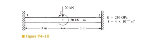
20 kN 210 GPa 1-4 × 10⁻⁴m4 20kN·m · Figure P4-10
structural analysis Figure Q() Question 2 For the bar assemblages shown in Figure Q(2), determine the nodal displacements, the forces in each element and the reactions. Use the direct stiffness me...
 structural analysis
Figure Q() Question 2 For the bar assemblages shown in Figure Q(2), determine the nodal displacements, the forces in each element and the reactions. Use the direct stiffness method (25 marks) 35 kN E-210 GPa 2 A4 x 10m2 1 m im
Figure Q() Question 2 For the bar assemblages shown in Figure Q(2), determine the nodal displacements, the forces in each element and the reactions. Use the direct stiffness method (25 marks) 35 kN E-210 GPa 2...
structural analysis
Figure Q() Question 2 For the bar assemblages shown in Figure Q(2), determine the nodal displacements, the forces in each element and the reactions. Use the direct stiffness method (25 marks) 35 kN E-210 GPa 2 A4 x 10m2 1 m im
Figure Q() Question 2 For the bar assemblages shown in Figure Q(2), determine the nodal displacements, the forces in each element and the reactions. Use the direct stiffness method (25 marks) 35 kN E-210 GPa 2...
Problem 2: a. For the plane truss shown in Figure 2, determine the nodal displacements, the element forces and stresses, and the support reactions. All elements have E-70 GPa and A-25 cm 100 k...
 Problem 2: a. For the plane truss shown in Figure 2, determine the nodal displacements, the element forces and stresses, and the support reactions. All elements have E-70 GPa and A-25 cm 100 kN 50 kN 50 kN 4 4 6 Figure 2. Plane Truss
Problem 2: a. For the plane truss shown in Figure 2, determine the nodal displacements, the element forces and stresses, and the support reactions. All elements have E-70 GPa and A-25 cm 100 kN 50...
Problem 2: a. For the plane truss shown in Figure 2, determine the nodal displacements, the element forces and stresses, and the support reactions. All elements have E-70 GPa and A-25 cm 100 kN 50 kN 50 kN 4 4 6 Figure 2. Plane Truss
Problem 2: a. For the plane truss shown in Figure 2, determine the nodal displacements, the element forces and stresses, and the support reactions. All elements have E-70 GPa and A-25 cm 100 kN 50...
Problem 2: For the beam shown in below figure, determine the nodal displacements and slopes, the...
 Problem 2: For the beam shown in below figure, determine the nodal displacements and slopes, the forces in each element, and the reactions. 4 kN/ Im E 70 GPa 13 x 10-4 m4 4 m
Determine the nodal displacements and find the reaction forces using the finite element method. Correct Answer:...
 Determine the nodal displacements and find the reaction forces
using the finite element method.
Correct Answer:
1 m 1000 kN - Determine displacements and reactions E = 210 GPa 1 for 1 and 2 A=6x10⁻⁴ m| E = 210 GPa 1 m →X A=672x10-4 m2 for 3 d2x = 11.91x10-m; dăx = 5.613x10-'m . Fix =-500kN; F1, =-500kN; F2y = 0; F;, = 707 kN
Determine the nodal displacements and find the reaction forces
using the finite element method.
Correct Answer:
1 m 1000 kN - Determine displacements and reactions E = 210 GPa 1 for 1 and 2 A=6x10⁻⁴ m| E = 210 GPa 1 m →X A=672x10-4 m2 for 3 d2x = 11.91x10-m; dăx = 5.613x10-'m . Fix =-500kN; F1, =-500kN; F2y = 0; F;, = 707 kN
problem 5-10 For the rigid frames shown in Figure, determine the displacements and rotations of the nodes the element forces, and the reactions. The values of E, A, and /to be used are listed next to...
 problem 5-10
For the rigid frames shown in Figure, determine the displacements and rotations of the nodes the element forces, and the reactions. The values of E, A, and /to be used are listed next to each figure. 10 KN E 210 GPa A x 10-2m 2 x 10-m O kN- m 10 kN Tm 5 kN m 45°
For the rigid frames shown in Figure, determine the displacements and rotations of the nodes the element forces, and the reactions....
problem 5-10
For the rigid frames shown in Figure, determine the displacements and rotations of the nodes the element forces, and the reactions. The values of E, A, and /to be used are listed next to each figure. 10 KN E 210 GPa A x 10-2m 2 x 10-m O kN- m 10 kN Tm 5 kN m 45°
For the rigid frames shown in Figure, determine the displacements and rotations of the nodes the element forces, and the reactions....
For the beam shown in below, determine the displacements and rotations at the nodes, the forces in each element, and reactions. Also, draw the shear force and bending moment diagrams 10 kN 2 E210 GPa...
 For the beam shown in below, determine the displacements and rotations at the nodes, the forces in each element, and reactions. Also, draw the shear force and bending moment diagrams 10 kN 2 E210 GPa .20 kN m
For the beam shown in below, determine the displacements and rotations at the nodes, the forces in each element, and reactions. Also, draw the shear force and bending moment diagrams 10 kN 2 E210 GPa .20 kN m
For the beam shown in below, determine the displacements and rotations at the nodes, the forces in each element, and reactions. Also, draw the shear force and bending moment diagrams 10 kN 2 E210 GPa .20 kN m
Solve all problems using the finite element stiffness method. For the rigid frame shown in Figure P5-4, determine (1) the nodal displacements and rotation at node 4, (2) the reactions, and (3) the fo...
 Solve all problems using the finite element stiffness method. For the rigid frame shown in Figure P5-4, determine (1) the nodal displacements and rotation at node 4, (2) the reactions, and (3) the forces in each element. Then check equilibrium at node 4 Finally, draw the shear force and bending moment diagrams for each element. Let E 30x 103 ksi, A 8 in2, and I 800 in.4 for all elements. 20 kip 25 ft 25 ft 40 ft Figure P5-4...
Problem 4, (20%) For the case shown determine the displacements and the slopes at the nodes,...
 Problem 4, (20%) For the case shown determine the displacements and the slopes at the nodes, the forces in each element, and the reactions. Also, draw the shear force and bending moment diagrams. 24 KN 4 m 4 m E = 70 GPa 1 = 2 x 10⁻⁴ m > k = 200 kN/m
Solve all problems using the finite element stiffness method.For the beams shown in Figure P4- 22...
 Solve all problems using the finite element stiffness method.For the beams shown in Figure P4- 22 determine the nodal displacements and slopes, the forces in each element, and the reactions. 4000 lb/ft E=29 × 106 psi 1 = 1 50 in.4 10 ft Figure P4-22
3.24 Determine the nodal displacements and the element forces for the truss shown in Figure P3-24. Assume all elements have the same AE 4 15 m 4 2 20 m Figure P3-24 3.24 Determine the nodal...
 3.24 Determine the nodal displacements and the element forces for the truss shown in Figure P3-24. Assume all elements have the same AE 4 15 m 4 2 20 m Figure P3-24
3.24 Determine the nodal displacements and the element forces for the truss shown in Figure P3-24. Assume all elements have the same AE
4 15 m 4 2 20 m Figure P3-24
3.24 Determine the nodal displacements and the element forces for the truss shown in Figure P3-24. Assume all elements have the same AE 4 15 m 4 2 20 m Figure P3-24
3.24 Determine the nodal displacements and the element forces for the truss shown in Figure P3-24. Assume all elements have the same AE
4 15 m 4 2 20 m Figure P3-24
 structural analysis
Figure Q() Question 2 For the bar assemblages shown in Figure Q(2), determine the nodal displacements, the forces in each element and the reactions. Use the direct stiffness method (25 marks) 35 kN E-210 GPa 2 A4 x 10m2 1 m im
Figure Q() Question 2 For the bar assemblages shown in Figure Q(2), determine the nodal displacements, the forces in each element and the reactions. Use the direct stiffness method (25 marks) 35 kN E-210 GPa 2...
structural analysis
Figure Q() Question 2 For the bar assemblages shown in Figure Q(2), determine the nodal displacements, the forces in each element and the reactions. Use the direct stiffness method (25 marks) 35 kN E-210 GPa 2 A4 x 10m2 1 m im
Figure Q() Question 2 For the bar assemblages shown in Figure Q(2), determine the nodal displacements, the forces in each element and the reactions. Use the direct stiffness method (25 marks) 35 kN E-210 GPa 2...
 Problem 2: a. For the plane truss shown in Figure 2, determine the nodal displacements, the element forces and stresses, and the support reactions. All elements have E-70 GPa and A-25 cm 100 kN 50 kN 50 kN 4 4 6 Figure 2. Plane Truss
Problem 2: a. For the plane truss shown in Figure 2, determine the nodal displacements, the element forces and stresses, and the support reactions. All elements have E-70 GPa and A-25 cm 100 kN 50...
Problem 2: a. For the plane truss shown in Figure 2, determine the nodal displacements, the element forces and stresses, and the support reactions. All elements have E-70 GPa and A-25 cm 100 kN 50 kN 50 kN 4 4 6 Figure 2. Plane Truss
Problem 2: a. For the plane truss shown in Figure 2, determine the nodal displacements, the element forces and stresses, and the support reactions. All elements have E-70 GPa and A-25 cm 100 kN 50...
 Problem 2: For the beam shown in below figure, determine the nodal displacements and slopes, the forces in each element, and the reactions. 4 kN/ Im E 70 GPa 13 x 10-4 m4 4 m
 Determine the nodal displacements and find the reaction forces
using the finite element method.
Correct Answer:
1 m 1000 kN - Determine displacements and reactions E = 210 GPa 1 for 1 and 2 A=6x10⁻⁴ m| E = 210 GPa 1 m →X A=672x10-4 m2 for 3 d2x = 11.91x10-m; dăx = 5.613x10-'m . Fix =-500kN; F1, =-500kN; F2y = 0; F;, = 707 kN
Determine the nodal displacements and find the reaction forces
using the finite element method.
Correct Answer:
1 m 1000 kN - Determine displacements and reactions E = 210 GPa 1 for 1 and 2 A=6x10⁻⁴ m| E = 210 GPa 1 m →X A=672x10-4 m2 for 3 d2x = 11.91x10-m; dăx = 5.613x10-'m . Fix =-500kN; F1, =-500kN; F2y = 0; F;, = 707 kN
 problem 5-10
For the rigid frames shown in Figure, determine the displacements and rotations of the nodes the element forces, and the reactions. The values of E, A, and /to be used are listed next to each figure. 10 KN E 210 GPa A x 10-2m 2 x 10-m O kN- m 10 kN Tm 5 kN m 45°
For the rigid frames shown in Figure, determine the displacements and rotations of the nodes the element forces, and the reactions....
problem 5-10
For the rigid frames shown in Figure, determine the displacements and rotations of the nodes the element forces, and the reactions. The values of E, A, and /to be used are listed next to each figure. 10 KN E 210 GPa A x 10-2m 2 x 10-m O kN- m 10 kN Tm 5 kN m 45°
For the rigid frames shown in Figure, determine the displacements and rotations of the nodes the element forces, and the reactions....
 For the beam shown in below, determine the displacements and rotations at the nodes, the forces in each element, and reactions. Also, draw the shear force and bending moment diagrams 10 kN 2 E210 GPa .20 kN m
For the beam shown in below, determine the displacements and rotations at the nodes, the forces in each element, and reactions. Also, draw the shear force and bending moment diagrams 10 kN 2 E210 GPa .20 kN m
For the beam shown in below, determine the displacements and rotations at the nodes, the forces in each element, and reactions. Also, draw the shear force and bending moment diagrams 10 kN 2 E210 GPa .20 kN m
 Solve all problems using the finite element stiffness method. For the rigid frame shown in Figure P5-4, determine (1) the nodal displacements and rotation at node 4, (2) the reactions, and (3) the forces in each element. Then check equilibrium at node 4 Finally, draw the shear force and bending moment diagrams for each element. Let E 30x 103 ksi, A 8 in2, and I 800 in.4 for all elements. 20 kip 25 ft 25 ft 40 ft Figure P5-4...
 Problem 4, (20%) For the case shown determine the displacements and the slopes at the nodes, the forces in each element, and the reactions. Also, draw the shear force and bending moment diagrams. 24 KN 4 m 4 m E = 70 GPa 1 = 2 x 10⁻⁴ m > k = 200 kN/m
 Solve all problems using the finite element stiffness method.For the beams shown in Figure P4- 22 determine the nodal displacements and slopes, the forces in each element, and the reactions. 4000 lb/ft E=29 × 106 psi 1 = 1 50 in.4 10 ft Figure P4-22
 3.24 Determine the nodal displacements and the element forces for the truss shown in Figure P3-24. Assume all elements have the same AE 4 15 m 4 2 20 m Figure P3-24
3.24 Determine the nodal displacements and the element forces for the truss shown in Figure P3-24. Assume all elements have the same AE
4 15 m 4 2 20 m Figure P3-24
3.24 Determine the nodal displacements and the element forces for the truss shown in Figure P3-24. Assume all elements have the same AE 4 15 m 4 2 20 m Figure P3-24
3.24 Determine the nodal displacements and the element forces for the truss shown in Figure P3-24. Assume all elements have the same AE
4 15 m 4 2 20 m Figure P3-24
Most questions answered within 3 hours.
-
Where is the error in this code sequence?
String s1 = "Hello";
String s2 = "ello";...
asked 11 months ago -
Financial data for Joel de Paris, Inc., for last year
follow:
Joel de Paris, Inc.
Balance...
asked 11 months ago -
Consider this reaction:
Al2(SO4)3 (aq)+ BaCl3
(aq) Al2Cl6 (aq)- +
3BaSO4(s) . What is the...
asked 11 months ago -
Suppose that Savneet is considering increasing her
recent random sample from 20 car rentals to 40...
asked 11 months ago -
Trucks arrive at an unloading terminal at an average rate of 120
per hour.
Trucks arrive...
asked 11 months ago -
Why are methanol and ethanol completely soluble in water while
octanol is not very little soluble....
asked 11 months ago -
A facilities manager at a university reads in a research report
that the mean amount of...
asked 11 months ago -
When the CuSO4 is rehydrated by adding water to the anhydrous
compound, is this an endothermic...
asked 11 months ago -
A ray of sunlight is passing from diamond into crown glass; the
angle of incidence is...
asked 11 months ago -
A block of mass 0.249 kg is placed on top of a light, vertical
spring of...
asked 11 months ago -
how do the kidneys compensate in the presences of acidosis
a) trigger hyperventilate
b) reserve acid...
asked 11 months ago -
Question 501 pts
The rental rate of capital to the firm increases. Which of the
following...
asked 11 months ago