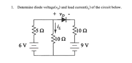
Determine diode voltage(Vd) and load current(IL) of the circuit
below
Homework Answers
Add Answer to:
Determine diode voltage(Vd) and load current(IL) of the circuit
below
1. Determine diode voltagelvp) and load...
Calculate the current flowing in the circuit below. The temperature is 300K. The battery voltage is...
 Calculate the current flowing in the circuit below. The temperature is 300K. The battery voltage is 5 V. The resistance R-1000 Ohms. The equation for current through the diode isi 10 9 [op{VANT) - 11 Amperes. Vd is the voltage drop across the diode and Vt is thermal voltage 1) Calculate the current flowing in the circuit below. The temperature is 300K. The battery voltage 15V. The resistance R-2000 Ohms. The equation for current through the diode is 19 (exp/Vd/T)...
The diode in the circuit below has a saturation current Is-10-13 A and n=1. Its ID-VD...
 The diode in the circuit below has a saturation current Is-10-13 A and n=1. Its ID-VD curve is illustrated below for your convenience. Problem 2 a) Using the graphical method, determine the value of R that would result in a diode current Ip -4mA. What is the resulting voltage Vp? b) With R as calculated above, a sinusoidal signal v, 100 sin(cot) mV is superimposed on the DC source. Draw the small signal model and find the output voltage across...
Part IIl: Diodes The Ideal-Diode Model a) For the circuit below, find ID and VD for the case VDD 5 V and R 10 k2. Assum...
 Part IIl: Diodes The Ideal-Diode Model a) For the circuit below, find ID and VD for the case VDD 5 V and R 10 k2. Assume that the diode has a voltage of 0.7 V at 1-mA current. Use (a) iteration and (b) the constant-voltage-drop model with VD 0.7 V 홍Yo b) Design the circuit below to provide an output voltage of 2.4 V. Assume that the diodes available have 0.7-V drop at 1 mA. +10 V Vo
Part IIl:...
Part IIl: Diodes The Ideal-Diode Model a) For the circuit below, find ID and VD for the case VDD 5 V and R 10 k2. Assume that the diode has a voltage of 0.7 V at 1-mA current. Use (a) iteration and (b) the constant-voltage-drop model with VD 0.7 V 홍Yo b) Design the circuit below to provide an output voltage of 2.4 V. Assume that the diodes available have 0.7-V drop at 1 mA. +10 V Vo
Part IIl:...
Calculate the (a) current flowing in the circuit below and (b) voltage drop across the resistor...
 Calculate the (a) current flowing in the circuit below and (b) voltage drop across the resistor Ron the right. The temperature is 600K. The battery voltage is 5 V. The resistance R-1 Giga Ohm. The equation for current through the diode is 1" 18 9 (exp/Vd/(2*VT)) - 1) Amperes. Vd is the voltage drop across the diode and VT is thermal voltage. Do not forget that this is diode with 2 as shown in the equation above. (1 Giga -...
Given the biased diode circuit below answer the following questions. Assume, lD = Is e vd/nUT,...
 Given the biased diode circuit below answer the following questions. Assume, lD = Is e vd/nUT, n =1, Cb is infinite, and vd = 600mV at 800uA, 50 points 2. VDD 200uA The current through each diode at VaV The small signal ac circuit, The transfer function. a. and voltage Cb Cb and Vc vin vout b. c. Va AC Vc 100uA
5. The diode reverse-saturation current is Is 1011 A Determine the diode current Id and voltage...
 5. The diode reverse-saturation current is Is 1011 A Determine the diode current Id and voltage Vd using a trial and error (iteration) and graphical analytic technique. R1 50k R2 30k D1 DIODE 〒 1.2 V
lDito .1111 86% 9:04 AM 1. Consider the circuit given below, where Vs 39 V. Make...
 lDito .1111 86% 9:04 AM 1. Consider the circuit given below, where Vs 39 V. Make all calculations based on the first approximation. Calculate the load voltage of the circuit, determine the load current of the circuit, determine the load power of the circuit, determine the diode power, determine the total power of the circuit V. 2. Consider the circuit given below, where Vs 12 V. Calculate the diode current when the polarity of the diode is reversed in the...
iin IL 25 V + + L CT 10VS 52 Vd The circuit given represents a...
 iin IL 25 V + + L CT 10VS 52 Vd The circuit given represents a simple buck convert. All the components can be considered ideal and the inductor current remains continuous. a) What is the average diode voltage ( va)? i) 12.5V iv) 15V iii) 25V ii) 10V b) What is the average current in the inductor (iL)? (25-10 10 iv) 25 ii) 5 25 i) L iii) L c) What is the average input current (im) ? (25-10)...
Can Someone explain how to do this problem? 4. Current and Voltage Source with Diode: For the circuit shown below, find...
 Can Someone explain how to do this problem?
4. Current and Voltage Source with Diode: For the circuit shown below, find the voltage vo. The current-voltage relationship for the diode is, as usual, Io(e"s/V 1) where Io 10-12 A and VT 0.026 V 10Ω 10 V (+ 5 mH Uo 1 A
4. Current and Voltage Source with Diode: For the circuit shown below, find the voltage vo. The current-voltage relationship for the diode is, as usual, Io(e"s/V 1) where...
Can Someone explain how to do this problem?
4. Current and Voltage Source with Diode: For the circuit shown below, find the voltage vo. The current-voltage relationship for the diode is, as usual, Io(e"s/V 1) where Io 10-12 A and VT 0.026 V 10Ω 10 V (+ 5 mH Uo 1 A
4. Current and Voltage Source with Diode: For the circuit shown below, find the voltage vo. The current-voltage relationship for the diode is, as usual, Io(e"s/V 1) where...
Problem 2 The diode in the circuit below has a saturation current Is = 10-13 A...
 Problem 2 The diode in the circuit below has a saturation current Is = 10-13 A and n=1. Its ID-VD curve is illustrated below for your convenience. a) Using the graphical method, determine the value of R that would result in a diode current Ip 4mA. What is the resulting voltage Vp? b) With R as calculated above, a sinusoidal signal v, 100 sin(ot) mV is superimposed on the DC source. Draw the small signal model and find the output...
 Calculate the current flowing in the circuit below. The temperature is 300K. The battery voltage is 5 V. The resistance R-1000 Ohms. The equation for current through the diode isi 10 9 [op{VANT) - 11 Amperes. Vd is the voltage drop across the diode and Vt is thermal voltage 1) Calculate the current flowing in the circuit below. The temperature is 300K. The battery voltage 15V. The resistance R-2000 Ohms. The equation for current through the diode is 19 (exp/Vd/T)...
 The diode in the circuit below has a saturation current Is-10-13 A and n=1. Its ID-VD curve is illustrated below for your convenience. Problem 2 a) Using the graphical method, determine the value of R that would result in a diode current Ip -4mA. What is the resulting voltage Vp? b) With R as calculated above, a sinusoidal signal v, 100 sin(cot) mV is superimposed on the DC source. Draw the small signal model and find the output voltage across...
 Part IIl: Diodes The Ideal-Diode Model a) For the circuit below, find ID and VD for the case VDD 5 V and R 10 k2. Assume that the diode has a voltage of 0.7 V at 1-mA current. Use (a) iteration and (b) the constant-voltage-drop model with VD 0.7 V 홍Yo b) Design the circuit below to provide an output voltage of 2.4 V. Assume that the diodes available have 0.7-V drop at 1 mA. +10 V Vo
Part IIl:...
Part IIl: Diodes The Ideal-Diode Model a) For the circuit below, find ID and VD for the case VDD 5 V and R 10 k2. Assume that the diode has a voltage of 0.7 V at 1-mA current. Use (a) iteration and (b) the constant-voltage-drop model with VD 0.7 V 홍Yo b) Design the circuit below to provide an output voltage of 2.4 V. Assume that the diodes available have 0.7-V drop at 1 mA. +10 V Vo
Part IIl:...
 Calculate the (a) current flowing in the circuit below and (b) voltage drop across the resistor Ron the right. The temperature is 600K. The battery voltage is 5 V. The resistance R-1 Giga Ohm. The equation for current through the diode is 1" 18 9 (exp/Vd/(2*VT)) - 1) Amperes. Vd is the voltage drop across the diode and VT is thermal voltage. Do not forget that this is diode with 2 as shown in the equation above. (1 Giga -...
 Given the biased diode circuit below answer the following questions. Assume, lD = Is e vd/nUT, n =1, Cb is infinite, and vd = 600mV at 800uA, 50 points 2. VDD 200uA The current through each diode at VaV The small signal ac circuit, The transfer function. a. and voltage Cb Cb and Vc vin vout b. c. Va AC Vc 100uA
 5. The diode reverse-saturation current is Is 1011 A Determine the diode current Id and voltage Vd using a trial and error (iteration) and graphical analytic technique. R1 50k R2 30k D1 DIODE 〒 1.2 V
 lDito .1111 86% 9:04 AM 1. Consider the circuit given below, where Vs 39 V. Make all calculations based on the first approximation. Calculate the load voltage of the circuit, determine the load current of the circuit, determine the load power of the circuit, determine the diode power, determine the total power of the circuit V. 2. Consider the circuit given below, where Vs 12 V. Calculate the diode current when the polarity of the diode is reversed in the...
 iin IL 25 V + + L CT 10VS 52 Vd The circuit given represents a simple buck convert. All the components can be considered ideal and the inductor current remains continuous. a) What is the average diode voltage ( va)? i) 12.5V iv) 15V iii) 25V ii) 10V b) What is the average current in the inductor (iL)? (25-10 10 iv) 25 ii) 5 25 i) L iii) L c) What is the average input current (im) ? (25-10)...
 Can Someone explain how to do this problem?
4. Current and Voltage Source with Diode: For the circuit shown below, find the voltage vo. The current-voltage relationship for the diode is, as usual, Io(e"s/V 1) where Io 10-12 A and VT 0.026 V 10Ω 10 V (+ 5 mH Uo 1 A
4. Current and Voltage Source with Diode: For the circuit shown below, find the voltage vo. The current-voltage relationship for the diode is, as usual, Io(e"s/V 1) where...
Can Someone explain how to do this problem?
4. Current and Voltage Source with Diode: For the circuit shown below, find the voltage vo. The current-voltage relationship for the diode is, as usual, Io(e"s/V 1) where Io 10-12 A and VT 0.026 V 10Ω 10 V (+ 5 mH Uo 1 A
4. Current and Voltage Source with Diode: For the circuit shown below, find the voltage vo. The current-voltage relationship for the diode is, as usual, Io(e"s/V 1) where...
 Problem 2 The diode in the circuit below has a saturation current Is = 10-13 A and n=1. Its ID-VD curve is illustrated below for your convenience. a) Using the graphical method, determine the value of R that would result in a diode current Ip 4mA. What is the resulting voltage Vp? b) With R as calculated above, a sinusoidal signal v, 100 sin(ot) mV is superimposed on the DC source. Draw the small signal model and find the output...
Most questions answered within 3 hours.
-
Where is the error in this code sequence?
String s1 = "Hello";
String s2 = "ello";...
asked 11 months ago -
Financial data for Joel de Paris, Inc., for last year
follow:
Joel de Paris, Inc.
Balance...
asked 11 months ago -
Consider this reaction:
Al2(SO4)3 (aq)+ BaCl3
(aq) Al2Cl6 (aq)- +
3BaSO4(s) . What is the...
asked 11 months ago -
Suppose that Savneet is considering increasing her
recent random sample from 20 car rentals to 40...
asked 11 months ago -
Trucks arrive at an unloading terminal at an average rate of 120
per hour.
Trucks arrive...
asked 11 months ago -
Why are methanol and ethanol completely soluble in water while
octanol is not very little soluble....
asked 11 months ago -
A facilities manager at a university reads in a research report
that the mean amount of...
asked 11 months ago -
When the CuSO4 is rehydrated by adding water to the anhydrous
compound, is this an endothermic...
asked 11 months ago -
A ray of sunlight is passing from diamond into crown glass; the
angle of incidence is...
asked 11 months ago -
A block of mass 0.249 kg is placed on top of a light, vertical
spring of...
asked 11 months ago -
how do the kidneys compensate in the presences of acidosis
a) trigger hyperventilate
b) reserve acid...
asked 11 months ago -
Question 501 pts
The rental rate of capital to the firm increases. Which of the
following...
asked 11 months ago