
Homework Answers
Add Answer to:
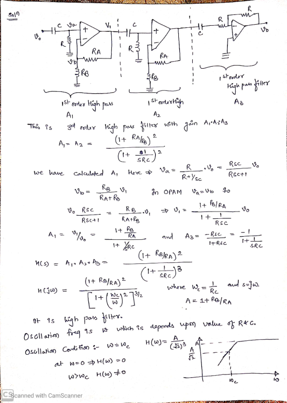
Q3 (40 p.) Find the oscillation frequency and oscillation condition for the circuit given below. *...
For the circuit below, calculate the time constant that defines the oscillation frequency of this circuit (i.e. the half period of the resulting oscillation T-1/(2fosc)), in seconds, to 1% accuracy....
 For the circuit below, calculate the time constant that defines the oscillation frequency of this circuit (i.e. the half period of the resulting oscillation T-1/(2fosc)), in seconds, to 1% accuracy. The op-amp has rail-to-rail swing, and a gain-bandwidth product of 3 MHz. The resistors used are r 3.0 k ohm, and the capacitor C 127.7 nF +15 V Vout 15 V Answer:
For the circuit below, calculate the time constant that defines the oscillation frequency of this circuit (i.e. the...
For the circuit below, calculate the time constant that defines the oscillation frequency of this circuit (i.e. the half period of the resulting oscillation T-1/(2fosc)), in seconds, to 1% accuracy. The op-amp has rail-to-rail swing, and a gain-bandwidth product of 3 MHz. The resistors used are r 3.0 k ohm, and the capacitor C 127.7 nF +15 V Vout 15 V Answer:
For the circuit below, calculate the time constant that defines the oscillation frequency of this circuit (i.e. the...
Data Converters and Timing Circuits (20 marks) (a) For the timing circuit shown below, use a 1000pF capacitor and find the values of RA and RB that result in an oscillation frequency of 100KHz an...
 Data Converters and Timing Circuits (20 marks) (a) For the timing circuit shown below, use a 1000pF capacitor and find the values of RA and RB that result in an oscillation frequency of 100KHz and a duty cycle of 75% Reset 0.693 R,+2R,)C Discharge Outpat Threshold Trigger Ground Duty-Cle2R R,+2R, ar (b) The 4-Bit Weighted-Resistor DAC Converter shown below is to be expanded into an 8-bit device a. What are the required values of the additional resistors to be added?...
II. (50 pts.) Find the frequency of oscillation of the circuit shown below. Find the minimum...
 II. (50 pts.) Find the frequency of oscillation of the circuit shown below. Find the minimum value of MOSFET gm required. Assume that ra= (Note: rd is also named ro) and C2 is a short circuit for any signal. AM Vout 5 0.12 10001 10K
+12 V Transfer curve for the given JFET Q3 (30 p.) For the given amplifier circuit,...
 +12 V Transfer curve for the given JFET Q3 (30 p.) For the given amplifier circuit, find input impedance (Zi), output impedance (Z.), voltage gain (V/V). *JFET is in saturation mode. 10ss 8 ma V = -6 V 3.32 O (vw) HE C с. int 2 -1 z 10 M2 VV 1. ΚΩ 20 uF
calculate the corner frequency of given circuit cuttoff frequency are given for these two circuits. 11...
 calculate the corner frequency of given circuit
cuttoff frequency are given for these two circuits.
11 R1 $ Record Sheet Table 12.1 Frequency 2 Vo (Fig-12-1) Vo (Fig-12-29 Vo (Fig-12-31 peale 10 100 IK EK 48 10k 12k 142 16k 18 22 ok 35k 40 BOK Experiment Na. 12: Passive Low-Press Filter Circuits Page 1 120K 200K IM Analysis 1. Calculate the comer frequences for Fig 2.1. Fig 12.2 & Fig 12.3. The cold - 1/RC) for Circuit 12.1 th-R/L...
calculate the corner frequency of given circuit
cuttoff frequency are given for these two circuits.
11 R1 $ Record Sheet Table 12.1 Frequency 2 Vo (Fig-12-1) Vo (Fig-12-29 Vo (Fig-12-31 peale 10 100 IK EK 48 10k 12k 142 16k 18 22 ok 35k 40 BOK Experiment Na. 12: Passive Low-Press Filter Circuits Page 1 120K 200K IM Analysis 1. Calculate the comer frequences for Fig 2.1. Fig 12.2 & Fig 12.3. The cold - 1/RC) for Circuit 12.1 th-R/L...
Can anyone show how to get the answer of 1.69? For the circuit below, we wish to change the frequency of oscillation from 1/(2 x R3x Cx log (3)-598.84159646502 Hz to 1/(2x R3 × C x loge(10-28 5.720053...
 Can
anyone show how to get the answer of 1.69?
For the circuit below, we wish to change the frequency of oscillation from 1/(2 x R3x Cx log (3)-598.84159646502 Hz to 1/(2x R3 × C x loge(10-28 5.72005388372 Hz. Initially R1: R2+ R3 = 7.6 k ohms. What value should R3 be changed to achieve this, in k ohms to with 1% accuracy? r2 +15 V r1 15 V 00 nF r3 PS. excuse the ridiculous precision on the freq....
Can
anyone show how to get the answer of 1.69?
For the circuit below, we wish to change the frequency of oscillation from 1/(2 x R3x Cx log (3)-598.84159646502 Hz to 1/(2x R3 × C x loge(10-28 5.72005388372 Hz. Initially R1: R2+ R3 = 7.6 k ohms. What value should R3 be changed to achieve this, in k ohms to with 1% accuracy? r2 +15 V r1 15 V 00 nF r3 PS. excuse the ridiculous precision on the freq....
2. In the circuit shown below, the operating frequency for the transmit antenna is 300 MHz....
 2. In the circuit shown below, the operating frequency for the transmit antenna is 300 MHz. At this frequency, we can represent the transmission line and antenna with a resistive load RL. This resistance accounts for radiated electromagnetic wave. The variable capacitor and inductor shown were tuned to achieve an impedance matching condition, i.e. where ZL is the impedance of the transmission line-antenna assembly and Zr is the Thévenin equivalent impedance of the driver circuit, including R., C and L....
please answer both questions in details Q3. For the circuit below, find: a) The voltage V,...
 please answer both questions in details
Q3. For the circuit below, find: a) The voltage V, in phasor form. b) The voltage v.(t) in time domain. 3221H + 10 cos( -45°) V TF + 5 sin(t + 30°) V 1 Q4. A capacitor consists of two concentric spherical conducting shells of radii a and b as shown in the figure. The space between them is filled with a radially inhomogeneous dielectric of permittivity e(r). The capacitance of this structure is...
please answer both questions in details
Q3. For the circuit below, find: a) The voltage V, in phasor form. b) The voltage v.(t) in time domain. 3221H + 10 cos( -45°) V TF + 5 sin(t + 30°) V 1 Q4. A capacitor consists of two concentric spherical conducting shells of radii a and b as shown in the figure. The space between them is filled with a radially inhomogeneous dielectric of permittivity e(r). The capacitance of this structure is...
Problem 3: /25 For the circuit shown below, use frequency-domain circuit analysis techniques to determine (a)...
 Problem 3: /25 For the circuit shown below, use frequency-domain circuit analysis techniques to determine (a) the voltage transfer function Ho) of the circuit; (b) the magnitude response H(@) of the circuit; and (c) the phase response (0) of the circuit. (d) Based on the results of parts (a) - (c), identify the type of filter circuit shown. с R + + Vin(t) 0000 L Vout(t)
Use source transformation to find the output current in the circuit given below, whero V, -...
 Use source transformation to find the output current in the circuit given below, whero V, - 40 230 V. X. 40 ,Xc 20, R = R2 = 800, and V, - 100 V. Please report your answer so the magnitude is positive and all angles are in the range of negative 180 degrees to positive 180 degrees. jXL R2 R -jXc V2 The output current in the given circuit is
 For the circuit below, calculate the time constant that defines the oscillation frequency of this circuit (i.e. the half period of the resulting oscillation T-1/(2fosc)), in seconds, to 1% accuracy. The op-amp has rail-to-rail swing, and a gain-bandwidth product of 3 MHz. The resistors used are r 3.0 k ohm, and the capacitor C 127.7 nF +15 V Vout 15 V Answer:
For the circuit below, calculate the time constant that defines the oscillation frequency of this circuit (i.e. the...
For the circuit below, calculate the time constant that defines the oscillation frequency of this circuit (i.e. the half period of the resulting oscillation T-1/(2fosc)), in seconds, to 1% accuracy. The op-amp has rail-to-rail swing, and a gain-bandwidth product of 3 MHz. The resistors used are r 3.0 k ohm, and the capacitor C 127.7 nF +15 V Vout 15 V Answer:
For the circuit below, calculate the time constant that defines the oscillation frequency of this circuit (i.e. the...
 Data Converters and Timing Circuits (20 marks) (a) For the timing circuit shown below, use a 1000pF capacitor and find the values of RA and RB that result in an oscillation frequency of 100KHz and a duty cycle of 75% Reset 0.693 R,+2R,)C Discharge Outpat Threshold Trigger Ground Duty-Cle2R R,+2R, ar (b) The 4-Bit Weighted-Resistor DAC Converter shown below is to be expanded into an 8-bit device a. What are the required values of the additional resistors to be added?...
 II. (50 pts.) Find the frequency of oscillation of the circuit shown below. Find the minimum value of MOSFET gm required. Assume that ra= (Note: rd is also named ro) and C2 is a short circuit for any signal. AM Vout 5 0.12 10001 10K
 +12 V Transfer curve for the given JFET Q3 (30 p.) For the given amplifier circuit, find input impedance (Zi), output impedance (Z.), voltage gain (V/V). *JFET is in saturation mode. 10ss 8 ma V = -6 V 3.32 O (vw) HE C с. int 2 -1 z 10 M2 VV 1. ΚΩ 20 uF
 calculate the corner frequency of given circuit
cuttoff frequency are given for these two circuits.
11 R1 $ Record Sheet Table 12.1 Frequency 2 Vo (Fig-12-1) Vo (Fig-12-29 Vo (Fig-12-31 peale 10 100 IK EK 48 10k 12k 142 16k 18 22 ok 35k 40 BOK Experiment Na. 12: Passive Low-Press Filter Circuits Page 1 120K 200K IM Analysis 1. Calculate the comer frequences for Fig 2.1. Fig 12.2 & Fig 12.3. The cold - 1/RC) for Circuit 12.1 th-R/L...
calculate the corner frequency of given circuit
cuttoff frequency are given for these two circuits.
11 R1 $ Record Sheet Table 12.1 Frequency 2 Vo (Fig-12-1) Vo (Fig-12-29 Vo (Fig-12-31 peale 10 100 IK EK 48 10k 12k 142 16k 18 22 ok 35k 40 BOK Experiment Na. 12: Passive Low-Press Filter Circuits Page 1 120K 200K IM Analysis 1. Calculate the comer frequences for Fig 2.1. Fig 12.2 & Fig 12.3. The cold - 1/RC) for Circuit 12.1 th-R/L...
 Can
anyone show how to get the answer of 1.69?
For the circuit below, we wish to change the frequency of oscillation from 1/(2 x R3x Cx log (3)-598.84159646502 Hz to 1/(2x R3 × C x loge(10-28 5.72005388372 Hz. Initially R1: R2+ R3 = 7.6 k ohms. What value should R3 be changed to achieve this, in k ohms to with 1% accuracy? r2 +15 V r1 15 V 00 nF r3 PS. excuse the ridiculous precision on the freq....
Can
anyone show how to get the answer of 1.69?
For the circuit below, we wish to change the frequency of oscillation from 1/(2 x R3x Cx log (3)-598.84159646502 Hz to 1/(2x R3 × C x loge(10-28 5.72005388372 Hz. Initially R1: R2+ R3 = 7.6 k ohms. What value should R3 be changed to achieve this, in k ohms to with 1% accuracy? r2 +15 V r1 15 V 00 nF r3 PS. excuse the ridiculous precision on the freq....
 2. In the circuit shown below, the operating frequency for the transmit antenna is 300 MHz. At this frequency, we can represent the transmission line and antenna with a resistive load RL. This resistance accounts for radiated electromagnetic wave. The variable capacitor and inductor shown were tuned to achieve an impedance matching condition, i.e. where ZL is the impedance of the transmission line-antenna assembly and Zr is the Thévenin equivalent impedance of the driver circuit, including R., C and L....
 please answer both questions in details
Q3. For the circuit below, find: a) The voltage V, in phasor form. b) The voltage v.(t) in time domain. 3221H + 10 cos( -45°) V TF + 5 sin(t + 30°) V 1 Q4. A capacitor consists of two concentric spherical conducting shells of radii a and b as shown in the figure. The space between them is filled with a radially inhomogeneous dielectric of permittivity e(r). The capacitance of this structure is...
please answer both questions in details
Q3. For the circuit below, find: a) The voltage V, in phasor form. b) The voltage v.(t) in time domain. 3221H + 10 cos( -45°) V TF + 5 sin(t + 30°) V 1 Q4. A capacitor consists of two concentric spherical conducting shells of radii a and b as shown in the figure. The space between them is filled with a radially inhomogeneous dielectric of permittivity e(r). The capacitance of this structure is...
 Problem 3: /25 For the circuit shown below, use frequency-domain circuit analysis techniques to determine (a) the voltage transfer function Ho) of the circuit; (b) the magnitude response H(@) of the circuit; and (c) the phase response (0) of the circuit. (d) Based on the results of parts (a) - (c), identify the type of filter circuit shown. с R + + Vin(t) 0000 L Vout(t)
 Use source transformation to find the output current in the circuit given below, whero V, - 40 230 V. X. 40 ,Xc 20, R = R2 = 800, and V, - 100 V. Please report your answer so the magnitude is positive and all angles are in the range of negative 180 degrees to positive 180 degrees. jXL R2 R -jXc V2 The output current in the given circuit is
Most questions answered within 3 hours.
-
Where is the error in this code sequence?
String s1 = "Hello";
String s2 = "ello";...
asked 10 months ago -
Financial data for Joel de Paris, Inc., for last year
follow:
Joel de Paris, Inc.
Balance...
asked 10 months ago -
Consider this reaction:
Al2(SO4)3 (aq)+ BaCl3
(aq) Al2Cl6 (aq)- +
3BaSO4(s) . What is the...
asked 10 months ago -
Suppose that Savneet is considering increasing her
recent random sample from 20 car rentals to 40...
asked 10 months ago -
Trucks arrive at an unloading terminal at an average rate of 120
per hour.
Trucks arrive...
asked 10 months ago -
Why are methanol and ethanol completely soluble in water while
octanol is not very little soluble....
asked 10 months ago -
A facilities manager at a university reads in a research report
that the mean amount of...
asked 10 months ago -
When the CuSO4 is rehydrated by adding water to the anhydrous
compound, is this an endothermic...
asked 10 months ago -
A ray of sunlight is passing from diamond into crown glass; the
angle of incidence is...
asked 10 months ago -
A block of mass 0.249 kg is placed on top of a light, vertical
spring of...
asked 10 months ago -
how do the kidneys compensate in the presences of acidosis
a) trigger hyperventilate
b) reserve acid...
asked 10 months ago -
Question 501 pts
The rental rate of capital to the firm increases. Which of the
following...
asked 10 months ago