Please solve this question with the Hardy Cross Method?

Homework Answers
r
Add Answer to:
Please solve this question with the Hardy Cross Method?
Determine the discharge in each pipe of...
re belowcalculated (2) If the flow into and out of a two-loop pipe system are as shown in the flow in each pipe using Hardy Cross method. The K value for each pipe from the pipe characteristics,...
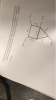 re belowcalculated (2) If the flow into and out of a two-loop pipe system are as shown in the flow in each pipe using Hardy Cross method. The K value for each pipe from the pipe characteristics, and n2. (maximum two iterations cac (28 Points) 50 cfs 25 cfs K=2 25 cfs 100 cfs
re belowcalculated (2) If the flow into and out of a two-loop pipe system are as shown in the flow in each pipe using Hardy Cross...
re belowcalculated (2) If the flow into and out of a two-loop pipe system are as shown in the flow in each pipe using Hardy Cross method. The K value for each pipe from the pipe characteristics, and n2. (maximum two iterations cac (28 Points) 50 cfs 25 cfs K=2 25 cfs 100 cfs
re belowcalculated (2) If the flow into and out of a two-loop pipe system are as shown in the flow in each pipe using Hardy Cross...
III. Explicit the Hardy-Cross method to determine the flow rate in each pipe of the following...
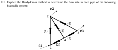 III. Explicit the Hardy-Cross method to determine the flow rate in each pipe of the following hydraulic system: 02 2 (4) (1) (5) 303 4 (3) 01 (2) 1
lculate the flow in each pipe using Hardy-Cross method. The diameter (inch) and length (feet) of...
 lculate the flow in each pipe using Hardy-Cross method. The diameter (inch) and length (feet) of pipe is given as shown in figure. Use Hazen william equation and consider C 0.35 cfs 0.42 cfs 2300 ft 12 in. 3.26 cfs 2 1100 ft 12 in. E 2.0 cfs 0.49 cfs
Question 1 The figure below shows a simple water pipe network. Relevant pipe properties are given...
 Question 1 The figure below shows a simple water pipe network. Relevant pipe properties are given in the figure and table below. The major losses of the pipes can be calculated by Darcy Weisbach equation. The friction factor () for all pipes is 0.015. Assuming that minor losses in the pipe network can be ignored and the pipe network is on a horizontal plane, determine the flow rates in all pipes using Hardy Cross method. Also, calculate the pressure head...
strength of material engineering of mechanical please solve this question 50 km 03: The pipe shown...
 strength of material
engineering of mechanical
please solve this question
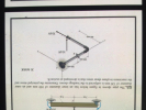
50 km 03: The pipe shown in figure below has an inner diameter of 100 mm and an outer diameter of 120 mm is subjected to the loadings shown. Determine the principal stress and the maximum in-plane shear stress that is developed af section B. 20 MARK 10 N 30 KN
strength of material
engineering of mechanical
please solve this question
50 km 03: The pipe shown in figure below has an inner diameter of 100 mm and an outer diameter of 120 mm is subjected to the loadings shown. Determine the principal stress and the maximum in-plane shear stress that is developed af section B. 20 MARK 10 N 30 KN
A pipe network is given below (Figure 2). All pipes are 1 km long, and 500...
 A pipe network is given below (Figure 2). All pipes are 1 km long, and 500 mm in diameter, with friction factor of 0 018 Determine the following. a) The value of Q (3) b) The correct flows in each pipe (using the Hardy-cross method) after the (17) first iteration [Hint: Assume Qo for pipe AB 105 L/s] c) The pressure heads at each node if the pressure head at reservoir A is 80 m. The elevation of each node...
Problem 5. Water is being pumped from the lower reservoir to the upper reservoir shown below...
 Problem 5. Water is being pumped from the lower reservoir to the upper reservoir shown below in Figure 5. Losses in this system follow the Darcy-Weisbach formula with B = 2 and the resistance coefficients in the two pipes are marked on the figure. The pump characteristic curve is given by the following equation: hp = 100-8260° where the head is in meters and the discharge Q is in m/s. Determine the discharge Q in the piping system using two...
Solve Problem 12.3, using the Cross technique. Problem 12.3 In the branched pipe system shown in...
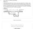 Solve Problem 12.3, using the Cross technique. Problem 12.3 In the branched pipe system shown in Fig. 12.8, 850 /min of water at 10°C is flowing in a DN 100 Schedule 40 pipe at A. The flow splits into two DN 50 Schedule 40 pipes as shown and then rejoins at B. Calculate (a) the flow rate in each of the branches and (b) the pressure difference pA-pB. Include the effect of the minor losses in the lower branch of...
Water flows through the pipe as shown in the below figure. Determine the net tension in...
 Water flows through the pipe as shown in the below figure. Determine the net tension in the bolts if minor losses are neglected and the wheels on which the pipe rests are frictionless. Please clearly show the steps of the trial & error method. Bolts 50 mm 10 m Cast Iron 20 m 30 m
Problem 1) The Figure below shows a pipe network with two tanks and assumed flow directions....
 Problem 1) The Figure below shows a pipe network with two tanks and assumed flow directions. Pipe details are shown in the table below. Determine the flow rate in each pipe using both the matrix method and the solver method Note: Grad students should solve for variable friction Given the pipe network below with values WS El. 410.0 ft WS El. 320.0 ft Pipe l 120 Length Diameter Line Nodes in. Elevation Demand A-1 1-2 1,000 12 0.019 0.019 2.0...
 re belowcalculated (2) If the flow into and out of a two-loop pipe system are as shown in the flow in each pipe using Hardy Cross method. The K value for each pipe from the pipe characteristics, and n2. (maximum two iterations cac (28 Points) 50 cfs 25 cfs K=2 25 cfs 100 cfs
re belowcalculated (2) If the flow into and out of a two-loop pipe system are as shown in the flow in each pipe using Hardy Cross...
re belowcalculated (2) If the flow into and out of a two-loop pipe system are as shown in the flow in each pipe using Hardy Cross method. The K value for each pipe from the pipe characteristics, and n2. (maximum two iterations cac (28 Points) 50 cfs 25 cfs K=2 25 cfs 100 cfs
re belowcalculated (2) If the flow into and out of a two-loop pipe system are as shown in the flow in each pipe using Hardy Cross...
 III. Explicit the Hardy-Cross method to determine the flow rate in each pipe of the following hydraulic system: 02 2 (4) (1) (5) 303 4 (3) 01 (2) 1
 lculate the flow in each pipe using Hardy-Cross method. The diameter (inch) and length (feet) of pipe is given as shown in figure. Use Hazen william equation and consider C 0.35 cfs 0.42 cfs 2300 ft 12 in. 3.26 cfs 2 1100 ft 12 in. E 2.0 cfs 0.49 cfs
 Question 1 The figure below shows a simple water pipe network. Relevant pipe properties are given in the figure and table below. The major losses of the pipes can be calculated by Darcy Weisbach equation. The friction factor () for all pipes is 0.015. Assuming that minor losses in the pipe network can be ignored and the pipe network is on a horizontal plane, determine the flow rates in all pipes using Hardy Cross method. Also, calculate the pressure head...
 strength of material
engineering of mechanical
please solve this question
50 km 03: The pipe shown in figure below has an inner diameter of 100 mm and an outer diameter of 120 mm is subjected to the loadings shown. Determine the principal stress and the maximum in-plane shear stress that is developed af section B. 20 MARK 10 N 30 KN
strength of material
engineering of mechanical
please solve this question
50 km 03: The pipe shown in figure below has an inner diameter of 100 mm and an outer diameter of 120 mm is subjected to the loadings shown. Determine the principal stress and the maximum in-plane shear stress that is developed af section B. 20 MARK 10 N 30 KN
 A pipe network is given below (Figure 2). All pipes are 1 km long, and 500 mm in diameter, with friction factor of 0 018 Determine the following. a) The value of Q (3) b) The correct flows in each pipe (using the Hardy-cross method) after the (17) first iteration [Hint: Assume Qo for pipe AB 105 L/s] c) The pressure heads at each node if the pressure head at reservoir A is 80 m. The elevation of each node...
 Problem 5. Water is being pumped from the lower reservoir to the upper reservoir shown below in Figure 5. Losses in this system follow the Darcy-Weisbach formula with B = 2 and the resistance coefficients in the two pipes are marked on the figure. The pump characteristic curve is given by the following equation: hp = 100-8260° where the head is in meters and the discharge Q is in m/s. Determine the discharge Q in the piping system using two...
 Solve Problem 12.3, using the Cross technique. Problem 12.3 In the branched pipe system shown in Fig. 12.8, 850 /min of water at 10°C is flowing in a DN 100 Schedule 40 pipe at A. The flow splits into two DN 50 Schedule 40 pipes as shown and then rejoins at B. Calculate (a) the flow rate in each of the branches and (b) the pressure difference pA-pB. Include the effect of the minor losses in the lower branch of...
 Water flows through the pipe as shown in the below figure. Determine the net tension in the bolts if minor losses are neglected and the wheels on which the pipe rests are frictionless. Please clearly show the steps of the trial & error method. Bolts 50 mm 10 m Cast Iron 20 m 30 m
 Problem 1) The Figure below shows a pipe network with two tanks and assumed flow directions. Pipe details are shown in the table below. Determine the flow rate in each pipe using both the matrix method and the solver method Note: Grad students should solve for variable friction Given the pipe network below with values WS El. 410.0 ft WS El. 320.0 ft Pipe l 120 Length Diameter Line Nodes in. Elevation Demand A-1 1-2 1,000 12 0.019 0.019 2.0...
Most questions answered within 3 hours.
-
Where is the error in this code sequence?
String s1 = "Hello";
String s2 = "ello";...
asked 11 months ago -
Financial data for Joel de Paris, Inc., for last year
follow:
Joel de Paris, Inc.
Balance...
asked 11 months ago -
Consider this reaction:
Al2(SO4)3 (aq)+ BaCl3
(aq) Al2Cl6 (aq)- +
3BaSO4(s) . What is the...
asked 11 months ago -
Suppose that Savneet is considering increasing her
recent random sample from 20 car rentals to 40...
asked 11 months ago -
Trucks arrive at an unloading terminal at an average rate of 120
per hour.
Trucks arrive...
asked 11 months ago -
Why are methanol and ethanol completely soluble in water while
octanol is not very little soluble....
asked 11 months ago -
A facilities manager at a university reads in a research report
that the mean amount of...
asked 11 months ago -
When the CuSO4 is rehydrated by adding water to the anhydrous
compound, is this an endothermic...
asked 11 months ago -
A ray of sunlight is passing from diamond into crown glass; the
angle of incidence is...
asked 11 months ago -
A block of mass 0.249 kg is placed on top of a light, vertical
spring of...
asked 11 months ago -
how do the kidneys compensate in the presences of acidosis
a) trigger hyperventilate
b) reserve acid...
asked 11 months ago -
Question 501 pts
The rental rate of capital to the firm increases. Which of the
following...
asked 11 months ago