Julius D. Cagampang's question:
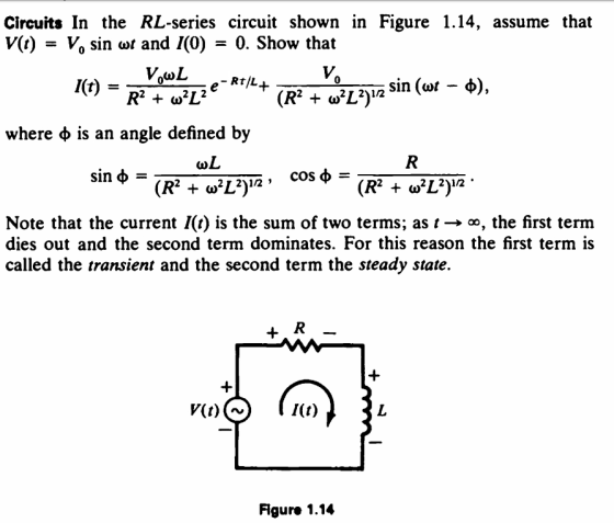
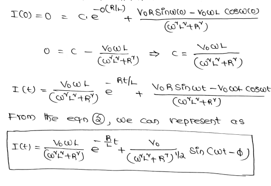
This is a solving problem with the use of the differential
equations. Help me to answer this. Thank you.
Homework Answers

![Up (t) = [vow Coswt - Voß sinwt cort A/ VO WL Coswt - Vo R sinwt ] conftar , JPCE) - VORSinot VO WL Coswt (WN+R)l2 Carthylla](http://img.homeworklib.com/questions/0c78ee60-eb11-11ea-b90f-e7ac8ba3b32b.png?x-oss-process=image/resize,w_560)
Add Answer to:
Julius D. Cagampang's question:
This is a solving problem with the use of the differential
equations....
6.3 Exercises In Exercises 1-5 find the current in the RLC circuit, assuming that E(t) =...
 6.3 Exercises In Exercises 1-5 find the current in the RLC circuit, assuming that E(t) = 0 fort > 0. 1. R = 3 ohms; L = 1 henrysC = .01 farads; Q. = 0 coulombs, 10 = 2 amperes. 11. Show that if E(t) = U coswt +V sin wt where U and V are constants then the steady state current in the RLC circuit shown in Figure 6.3.1 is w?RE(t) + (1/C - Lw?) E' (t) I where...
The equations for the charge Q(t) and current i (t) in the following LRC circuit are Question 3 (...
 3
The equations for the charge Q(t) and current i (t) in the following LRC circuit are Question 3 (5 points) Saved 0 amps dt C 10 amps i(t) dt 10 amps where the applied voltage VA -Vp V cos at as soon as the switch S is closed at t 0 Question 4 (5 points Saved ift) 10 amps -10 amps 0 amps Qrt The general solution is: please hand in at your recitation, the graphs of when Q(0)-i(0-0,...
3
The equations for the charge Q(t) and current i (t) in the following LRC circuit are Question 3 (5 points) Saved 0 amps dt C 10 amps i(t) dt 10 amps where the applied voltage VA -Vp V cos at as soon as the switch S is closed at t 0 Question 4 (5 points Saved ift) 10 amps -10 amps 0 amps Qrt The general solution is: please hand in at your recitation, the graphs of when Q(0)-i(0-0,...
R t = i(t) C 2011P E e p gP a P9.09 10ed The voltage applied...
 R t = i(t) C 2011P E e p gP a P9.09 10ed The voltage applied to this circuit at t 0 (when the switch closes) is v (t) = 75 cos (4,000t - 60°) Volts Also given that R = 400 2 (0hm) and L=75 mH (milli Henry) The initial inductor current is zero for t< 0 The textbook gives you the total response equation as: )_ ?(0-¢)so R2+(w L) Cos(wt+¢-e) -V V m i(t)=itransient(t)+isteady.state(t)=R2 +(wL m - ㅎCOS...
Solve each practice problem. TYPE solutions in engineering notation TYPE solutions in engineering notation. Calcula...
 Solve each practice problem. TYPE solutions in
engineering notation
TYPE solutions in engineering
notation.
Calculate the component voltages and branch currents for the circuit shown in Figure 6.40, along with the values of I, and Rr. 3. R3 2 kn R4 4.7 k R1 10 k Vs 26 V R5 3.3 k R2 3 kn FIGURE 6.40 Calculate the component currents and loop voltages for the circuit shown in Figure 6.42, along with the values of I and Rr 5....
Solve each practice problem. TYPE solutions in
engineering notation
TYPE solutions in engineering
notation.
Calculate the component voltages and branch currents for the circuit shown in Figure 6.40, along with the values of I, and Rr. 3. R3 2 kn R4 4.7 k R1 10 k Vs 26 V R5 3.3 k R2 3 kn FIGURE 6.40 Calculate the component currents and loop voltages for the circuit shown in Figure 6.42, along with the values of I and Rr 5....
5) Consider the following second-order bandpass filter. As input voltage, apply V(t) 100Ω, C-4.7 μF. and L-10mH. sin(wt).R in Vout Fig 9: Second-order band-pass filter a) Determine the frequenc...
 5) Consider the following second-order bandpass filter. As input voltage, apply V(t) 100Ω, C-4.7 μF. and L-10mH. sin(wt).R in Vout Fig 9: Second-order band-pass filter a) Determine the frequency response function H(ju) Ve-ju) / Vm(ju) and sketch the magnitude and phase characteristics versus w by calaulation. Calculate the theoretical cutoff frequency of the filter Using PSpice AC analysis, plot magnitude lHju)l and phase ф characteristics of the filter, between 1 Hz-100 KHz b) c)
5) Consider the following second-order bandpass...
5) Consider the following second-order bandpass filter. As input voltage, apply V(t) 100Ω, C-4.7 μF. and L-10mH. sin(wt).R in Vout Fig 9: Second-order band-pass filter a) Determine the frequency response function H(ju) Ve-ju) / Vm(ju) and sketch the magnitude and phase characteristics versus w by calaulation. Calculate the theoretical cutoff frequency of the filter Using PSpice AC analysis, plot magnitude lHju)l and phase ф characteristics of the filter, between 1 Hz-100 KHz b) c)
5) Consider the following second-order bandpass...
Q2) A single phase half-wave uncontrolled rectifier with RL load is shown below With R-1000 L 01H w-377rad/s and V 1...
 Q2) A single phase half-wave uncontrolled rectifier with RL load is shown below With R-1000 L 01H w-377rad/s and V 100V, Determine a) An expression for the load current i(t). b) The value of the current at t 16 ms c) The average load current (10 marks) 7 RV そ0 -121 34.7 Vsinfwr) + VE 0.360
Q2) A single phase half-wave uncontrolled rectifier with RL load is shown below With R-1000 L 01H w-377rad/s and V 100V, Determine a) An...
Q2) A single phase half-wave uncontrolled rectifier with RL load is shown below With R-1000 L 01H w-377rad/s and V 100V, Determine a) An expression for the load current i(t). b) The value of the current at t 16 ms c) The average load current (10 marks) 7 RV そ0 -121 34.7 Vsinfwr) + VE 0.360
Q2) A single phase half-wave uncontrolled rectifier with RL load is shown below With R-1000 L 01H w-377rad/s and V 100V, Determine a) An...
Please solve this as a differential equations problem not as a physics probelm, please. 3. (7pts)...
 Please solve this as a differential
equations problem not as a physics probelm, please.
3. (7pts) A crude tuning device can be created by an LRC-circuit forced by an external signal. An LRC-circuit is equipped with a variable capacitor, which can be dialed to different values to obtain the maximum response from an incoming radio signal. If I(t) is the current in the tuning device, which contains an inductor, L, a resistor, R, and a tunable capacitor, C, and receives...
Please solve this as a differential
equations problem not as a physics probelm, please.
3. (7pts) A crude tuning device can be created by an LRC-circuit forced by an external signal. An LRC-circuit is equipped with a variable capacitor, which can be dialed to different values to obtain the maximum response from an incoming radio signal. If I(t) is the current in the tuning device, which contains an inductor, L, a resistor, R, and a tunable capacitor, C, and receives...
do the part on red please. 1. Validate conclusions regarding the behavior of inductors in transient...
 do the part on red please.
1. Validate conclusions regarding the behavior of inductors in transient and steady-state DC network. 2. Verify basic equations for determining the total induction in series, parallel and series-parallel circuits. 3. Use simulation software to understand circuit characteristics. EQUIPMENT REQUIRED: Multisim tool. PROCEDURES: Part 1. Series RL Circuits Use the circuit of Figure 4 (pick RL=202). a. Calculate the steady-state values of IL and VL. IL = 20.4 mA VL = _0.408_V IL=10 / (470...
do the part on red please.
1. Validate conclusions regarding the behavior of inductors in transient and steady-state DC network. 2. Verify basic equations for determining the total induction in series, parallel and series-parallel circuits. 3. Use simulation software to understand circuit characteristics. EQUIPMENT REQUIRED: Multisim tool. PROCEDURES: Part 1. Series RL Circuits Use the circuit of Figure 4 (pick RL=202). a. Calculate the steady-state values of IL and VL. IL = 20.4 mA VL = _0.408_V IL=10 / (470...
(a) Show that the system of differential equations for the currents iz(t) and iz(t) in the...
 (a) Show that the system of differential equations for the currents iz(t) and iz(t) in the electrical network shown in the figure below is di2 41 + RI2 + Riz = E(t) dt di3 L2 + RI2 + Riz = E(t). dt R 13 41 i2 E ᏪᎲ L lllll L2 By Kirchhoff's first law we have the following relationship between 11, 12, and iz. 11 - 12+ iz By applying Kirchhoff's second law to the iq, iz loop, we...
Use Thevenin’s theorem to calculate a, b, c, d and e only a) The current through...
 Use
Thevenin’s theorem to calculate a, b, c, d and e only
a) The current through the load resistor (I); b) The voltage across the load resistor (V): c) I short circuit (I); d) V open circuit (V). This is the Thevenin voltage (E); .) The resistance (R) between the terminals A and B with the power supplies replaced by their internal resistances. This is the Thevenin resistance (R ). 2. Using the values obtained in Part 1 for E...
Use
Thevenin’s theorem to calculate a, b, c, d and e only
a) The current through the load resistor (I); b) The voltage across the load resistor (V): c) I short circuit (I); d) V open circuit (V). This is the Thevenin voltage (E); .) The resistance (R) between the terminals A and B with the power supplies replaced by their internal resistances. This is the Thevenin resistance (R ). 2. Using the values obtained in Part 1 for E...
 6.3 Exercises In Exercises 1-5 find the current in the RLC circuit, assuming that E(t) = 0 fort > 0. 1. R = 3 ohms; L = 1 henrysC = .01 farads; Q. = 0 coulombs, 10 = 2 amperes. 11. Show that if E(t) = U coswt +V sin wt where U and V are constants then the steady state current in the RLC circuit shown in Figure 6.3.1 is w?RE(t) + (1/C - Lw?) E' (t) I where...
 3
The equations for the charge Q(t) and current i (t) in the following LRC circuit are Question 3 (5 points) Saved 0 amps dt C 10 amps i(t) dt 10 amps where the applied voltage VA -Vp V cos at as soon as the switch S is closed at t 0 Question 4 (5 points Saved ift) 10 amps -10 amps 0 amps Qrt The general solution is: please hand in at your recitation, the graphs of when Q(0)-i(0-0,...
3
The equations for the charge Q(t) and current i (t) in the following LRC circuit are Question 3 (5 points) Saved 0 amps dt C 10 amps i(t) dt 10 amps where the applied voltage VA -Vp V cos at as soon as the switch S is closed at t 0 Question 4 (5 points Saved ift) 10 amps -10 amps 0 amps Qrt The general solution is: please hand in at your recitation, the graphs of when Q(0)-i(0-0,...
 R t = i(t) C 2011P E e p gP a P9.09 10ed The voltage applied to this circuit at t 0 (when the switch closes) is v (t) = 75 cos (4,000t - 60°) Volts Also given that R = 400 2 (0hm) and L=75 mH (milli Henry) The initial inductor current is zero for t< 0 The textbook gives you the total response equation as: )_ ?(0-¢)so R2+(w L) Cos(wt+¢-e) -V V m i(t)=itransient(t)+isteady.state(t)=R2 +(wL m - ㅎCOS...
 Solve each practice problem. TYPE solutions in
engineering notation
TYPE solutions in engineering
notation.
Calculate the component voltages and branch currents for the circuit shown in Figure 6.40, along with the values of I, and Rr. 3. R3 2 kn R4 4.7 k R1 10 k Vs 26 V R5 3.3 k R2 3 kn FIGURE 6.40 Calculate the component currents and loop voltages for the circuit shown in Figure 6.42, along with the values of I and Rr 5....
Solve each practice problem. TYPE solutions in
engineering notation
TYPE solutions in engineering
notation.
Calculate the component voltages and branch currents for the circuit shown in Figure 6.40, along with the values of I, and Rr. 3. R3 2 kn R4 4.7 k R1 10 k Vs 26 V R5 3.3 k R2 3 kn FIGURE 6.40 Calculate the component currents and loop voltages for the circuit shown in Figure 6.42, along with the values of I and Rr 5....
 5) Consider the following second-order bandpass filter. As input voltage, apply V(t) 100Ω, C-4.7 μF. and L-10mH. sin(wt).R in Vout Fig 9: Second-order band-pass filter a) Determine the frequency response function H(ju) Ve-ju) / Vm(ju) and sketch the magnitude and phase characteristics versus w by calaulation. Calculate the theoretical cutoff frequency of the filter Using PSpice AC analysis, plot magnitude lHju)l and phase ф characteristics of the filter, between 1 Hz-100 KHz b) c)
5) Consider the following second-order bandpass...
5) Consider the following second-order bandpass filter. As input voltage, apply V(t) 100Ω, C-4.7 μF. and L-10mH. sin(wt).R in Vout Fig 9: Second-order band-pass filter a) Determine the frequency response function H(ju) Ve-ju) / Vm(ju) and sketch the magnitude and phase characteristics versus w by calaulation. Calculate the theoretical cutoff frequency of the filter Using PSpice AC analysis, plot magnitude lHju)l and phase ф characteristics of the filter, between 1 Hz-100 KHz b) c)
5) Consider the following second-order bandpass...
 Q2) A single phase half-wave uncontrolled rectifier with RL load is shown below With R-1000 L 01H w-377rad/s and V 100V, Determine a) An expression for the load current i(t). b) The value of the current at t 16 ms c) The average load current (10 marks) 7 RV そ0 -121 34.7 Vsinfwr) + VE 0.360
Q2) A single phase half-wave uncontrolled rectifier with RL load is shown below With R-1000 L 01H w-377rad/s and V 100V, Determine a) An...
Q2) A single phase half-wave uncontrolled rectifier with RL load is shown below With R-1000 L 01H w-377rad/s and V 100V, Determine a) An expression for the load current i(t). b) The value of the current at t 16 ms c) The average load current (10 marks) 7 RV そ0 -121 34.7 Vsinfwr) + VE 0.360
Q2) A single phase half-wave uncontrolled rectifier with RL load is shown below With R-1000 L 01H w-377rad/s and V 100V, Determine a) An...
 Please solve this as a differential
equations problem not as a physics probelm, please.
3. (7pts) A crude tuning device can be created by an LRC-circuit forced by an external signal. An LRC-circuit is equipped with a variable capacitor, which can be dialed to different values to obtain the maximum response from an incoming radio signal. If I(t) is the current in the tuning device, which contains an inductor, L, a resistor, R, and a tunable capacitor, C, and receives...
Please solve this as a differential
equations problem not as a physics probelm, please.
3. (7pts) A crude tuning device can be created by an LRC-circuit forced by an external signal. An LRC-circuit is equipped with a variable capacitor, which can be dialed to different values to obtain the maximum response from an incoming radio signal. If I(t) is the current in the tuning device, which contains an inductor, L, a resistor, R, and a tunable capacitor, C, and receives...
 do the part on red please.
1. Validate conclusions regarding the behavior of inductors in transient and steady-state DC network. 2. Verify basic equations for determining the total induction in series, parallel and series-parallel circuits. 3. Use simulation software to understand circuit characteristics. EQUIPMENT REQUIRED: Multisim tool. PROCEDURES: Part 1. Series RL Circuits Use the circuit of Figure 4 (pick RL=202). a. Calculate the steady-state values of IL and VL. IL = 20.4 mA VL = _0.408_V IL=10 / (470...
do the part on red please.
1. Validate conclusions regarding the behavior of inductors in transient and steady-state DC network. 2. Verify basic equations for determining the total induction in series, parallel and series-parallel circuits. 3. Use simulation software to understand circuit characteristics. EQUIPMENT REQUIRED: Multisim tool. PROCEDURES: Part 1. Series RL Circuits Use the circuit of Figure 4 (pick RL=202). a. Calculate the steady-state values of IL and VL. IL = 20.4 mA VL = _0.408_V IL=10 / (470...
 (a) Show that the system of differential equations for the currents iz(t) and iz(t) in the electrical network shown in the figure below is di2 41 + RI2 + Riz = E(t) dt di3 L2 + RI2 + Riz = E(t). dt R 13 41 i2 E ᏪᎲ L lllll L2 By Kirchhoff's first law we have the following relationship between 11, 12, and iz. 11 - 12+ iz By applying Kirchhoff's second law to the iq, iz loop, we...
 Use
Thevenin’s theorem to calculate a, b, c, d and e only
a) The current through the load resistor (I); b) The voltage across the load resistor (V): c) I short circuit (I); d) V open circuit (V). This is the Thevenin voltage (E); .) The resistance (R) between the terminals A and B with the power supplies replaced by their internal resistances. This is the Thevenin resistance (R ). 2. Using the values obtained in Part 1 for E...
Use
Thevenin’s theorem to calculate a, b, c, d and e only
a) The current through the load resistor (I); b) The voltage across the load resistor (V): c) I short circuit (I); d) V open circuit (V). This is the Thevenin voltage (E); .) The resistance (R) between the terminals A and B with the power supplies replaced by their internal resistances. This is the Thevenin resistance (R ). 2. Using the values obtained in Part 1 for E...
Most questions answered within 3 hours.
-
Where is the error in this code sequence?
String s1 = "Hello";
String s2 = "ello";...
asked 10 months ago -
Financial data for Joel de Paris, Inc., for last year
follow:
Joel de Paris, Inc.
Balance...
asked 10 months ago -
Consider this reaction:
Al2(SO4)3 (aq)+ BaCl3
(aq) Al2Cl6 (aq)- +
3BaSO4(s) . What is the...
asked 10 months ago -
Suppose that Savneet is considering increasing her
recent random sample from 20 car rentals to 40...
asked 10 months ago -
Trucks arrive at an unloading terminal at an average rate of 120
per hour.
Trucks arrive...
asked 10 months ago -
Why are methanol and ethanol completely soluble in water while
octanol is not very little soluble....
asked 10 months ago -
A facilities manager at a university reads in a research report
that the mean amount of...
asked 10 months ago -
When the CuSO4 is rehydrated by adding water to the anhydrous
compound, is this an endothermic...
asked 10 months ago -
A ray of sunlight is passing from diamond into crown glass; the
angle of incidence is...
asked 10 months ago -
A block of mass 0.249 kg is placed on top of a light, vertical
spring of...
asked 10 months ago -
how do the kidneys compensate in the presences of acidosis
a) trigger hyperventilate
b) reserve acid...
asked 10 months ago -
Question 501 pts
The rental rate of capital to the firm increases. Which of the
following...
asked 10 months ago