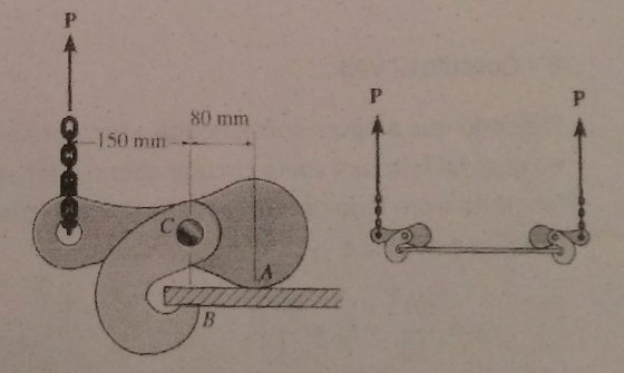
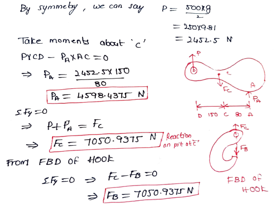
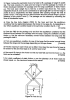
3- The hooks shown in the figure are used to lift a 500 kg smooth plate.
- Determine the resulting compressive force that the hook exerts on the plate at points A and B.
- The reaction on pin C.
Homework Answers
THANK YOU VERY MUCH!!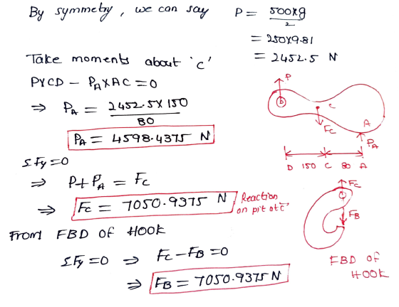
Add Answer to:
3- The hooks shown in the figure are used to lift a 500 kg smooth plate....
Two slots have been cut in the plate shown. The plate has been placed so that...
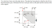 Two slots have been cut in the plate shown. The plate has been placed so that the slots fit two fixed frictionless pins. Determine the force each pin exerts on the plate and the reaction at the roller support. 100 mm 50 N 70 mm 100 mm 30° I 200 mm 30 100 mm 50 N 180 mm 220 mm
Two rigid bodies, 2 and 3, are connected by three springs as shown in the figure....
 Two rigid bodies, 2 and 3, are connected by three springs as shown in the figure. A horizontal force of 1,000 N is applied on Body 3 as shown in the figure. Find the displacements of the three bodies and the forces (tensile/compressive) in the springs. What is the reaction at the wall? Assume the bodies can undergo only translation in the horizontal direction. The spring constants (N/mm) are kg = 400 kg = 500 ks = 500 N mm...
The 0.2-kg pin P is constrained to move in the smooth curved slot, which is defined...
 The 0.2-kg pin P is constrained to move in the smooth curved slot, which is defined by the lemniscate r = (0.6 cos2θ) m. Its motion is controlled by the rotation of the slotted arm OA. which has a constant clockwise angular velocity of theta = -3 rad/s. (Figure 1)
Determine the force arm OA exerts on the pin P when θ = 0°. Motion is in the vertical plane. Express your answer to three significant figures and include...
The 0.2-kg pin P is constrained to move in the smooth curved slot, which is defined by the lemniscate r = (0.6 cos2θ) m. Its motion is controlled by the rotation of the slotted arm OA. which has a constant clockwise angular velocity of theta = -3 rad/s. (Figure 1)
Determine the force arm OA exerts on the pin P when θ = 0°. Motion is in the vertical plane. Express your answer to three significant figures and include...
A riveted structural connection supports a load P = 10 KN, as shown in the figure...
 A riveted structural connection supports a load P = 10 KN, as shown in the figure below. What is the value of the force on the most heavily loaded rivet in the bracket? Determine the value of the bearing stress if the plate is 15 mm thick. The line of action of the applied load passes through point D. 5 at 60 = 300 mm 150 mm Bracket 20 mm rivets Gusset plate Р Page 2 of 3
1. The 100 kg weight on hydraulic lift (area = 0.6 m²) shown in figure. At...
 1. The 100 kg weight on hydraulic lift (area = 0.6 m²) shown in figure. At points A, B C and D calculate the pressure. (Ywater=9810 N/m?) Hinge 2. a) Determine the resultant force acting on the inclined circular gate. b) Find the location of center of pressure. c) Calculate the minimum weight of the block that can open the gate. (Assume that gate is weightless) (a=80 cm, water 9810 N/m) 3. The length of submerged gate AB is 5...
The pulley system shown in Figure 6-25 is used to lift a 62 kg crate. Note...
The pulley system shown in Figure 6-25 is used to lift a 62 kg crate. Note that one chain connects the upper pulley to the ceiling and a second chain connects the lower pulley to the crate. Assume that the masses of the chains, pulleys, and ropes are negligible and the crate is rising with an acceleration of 1.7 m/s2. Figure 6-25 (a) Determine the force. kN (b) Determine the tension in the upper chain. kN (c) Determine the tension...
(6 Points) - Problem 3: A 3000 kg truck is being used to lift a 800...
 (6 Points) - Problem 3: A 3000 kg truck is being used to lift a 800 kg boulder B that is on a 100 kg pallet A. Knowing that the acceleration of the rear wheel drive truck is 2 m/s", determine (a) the reaction at each of the front wheels. (b) the force between the boulder and the pallet. Im 0.6 m
3. Figure 3 shows the symmetric hook of a hoist to lift a package of weight...
 3. Figure 3 shows the symmetric hook of a hoist to lift a package of weight G (width 2a). The hook consists of a plate and two tongs to hold the package by means of friction developed between the package and the tongs (coefficient of static friction Ho). The hook (own weight Go) is held by a central rope (force So). Two ropes (respective forces Si and S2) are connected at a right angle (90°) to the two tongs in...
The 0.3-kg pin P is constrained to move in the smooth curved slot, which is defined...
 The 0.3-kg pin P is constrained to move in the smooth curved slot, which is defined by the lemniscate (0.6 cos20) m. Its motion is controlled by the rotation of the slotted arm O A, which has a constant clockwise angular velocity of 0 = -3 rad/s. (Figure 1) r= Part A Determine the force arm O A exerts on the pin P when 0 = 0°. Motion is in the vertical plane. Express your answer to three significant figures...
Diameter of pin 2 mm. All pins are in single shear. Question 1: A light plane...
 Diameter of pin 2 mm. All pins are in single shear.
Question 1: A light plane structure is supported by a roller at A and a pin at D and is subjected to a load of Pat F as shown in the figure. All the members have rectangular cross section with height 5 mm and thickness 1 mm. Tensile/Compressive strength of the members = 80 MPa, Shear strength of the pin = 50 MPa. Consider an appropriate factor of safety....
Diameter of pin 2 mm. All pins are in single shear.
Question 1: A light plane structure is supported by a roller at A and a pin at D and is subjected to a load of Pat F as shown in the figure. All the members have rectangular cross section with height 5 mm and thickness 1 mm. Tensile/Compressive strength of the members = 80 MPa, Shear strength of the pin = 50 MPa. Consider an appropriate factor of safety....
 Two slots have been cut in the plate shown. The plate has been placed so that the slots fit two fixed frictionless pins. Determine the force each pin exerts on the plate and the reaction at the roller support. 100 mm 50 N 70 mm 100 mm 30° I 200 mm 30 100 mm 50 N 180 mm 220 mm
 Two rigid bodies, 2 and 3, are connected by three springs as shown in the figure. A horizontal force of 1,000 N is applied on Body 3 as shown in the figure. Find the displacements of the three bodies and the forces (tensile/compressive) in the springs. What is the reaction at the wall? Assume the bodies can undergo only translation in the horizontal direction. The spring constants (N/mm) are kg = 400 kg = 500 ks = 500 N mm...
 The 0.2-kg pin P is constrained to move in the smooth curved slot, which is defined by the lemniscate r = (0.6 cos2θ) m. Its motion is controlled by the rotation of the slotted arm OA. which has a constant clockwise angular velocity of theta = -3 rad/s. (Figure 1)
Determine the force arm OA exerts on the pin P when θ = 0°. Motion is in the vertical plane. Express your answer to three significant figures and include...
The 0.2-kg pin P is constrained to move in the smooth curved slot, which is defined by the lemniscate r = (0.6 cos2θ) m. Its motion is controlled by the rotation of the slotted arm OA. which has a constant clockwise angular velocity of theta = -3 rad/s. (Figure 1)
Determine the force arm OA exerts on the pin P when θ = 0°. Motion is in the vertical plane. Express your answer to three significant figures and include...
 A riveted structural connection supports a load P = 10 KN, as shown in the figure below. What is the value of the force on the most heavily loaded rivet in the bracket? Determine the value of the bearing stress if the plate is 15 mm thick. The line of action of the applied load passes through point D. 5 at 60 = 300 mm 150 mm Bracket 20 mm rivets Gusset plate Р Page 2 of 3
 1. The 100 kg weight on hydraulic lift (area = 0.6 m²) shown in figure. At points A, B C and D calculate the pressure. (Ywater=9810 N/m?) Hinge 2. a) Determine the resultant force acting on the inclined circular gate. b) Find the location of center of pressure. c) Calculate the minimum weight of the block that can open the gate. (Assume that gate is weightless) (a=80 cm, water 9810 N/m) 3. The length of submerged gate AB is 5...
 (6 Points) - Problem 3: A 3000 kg truck is being used to lift a 800 kg boulder B that is on a 100 kg pallet A. Knowing that the acceleration of the rear wheel drive truck is 2 m/s", determine (a) the reaction at each of the front wheels. (b) the force between the boulder and the pallet. Im 0.6 m
 3. Figure 3 shows the symmetric hook of a hoist to lift a package of weight G (width 2a). The hook consists of a plate and two tongs to hold the package by means of friction developed between the package and the tongs (coefficient of static friction Ho). The hook (own weight Go) is held by a central rope (force So). Two ropes (respective forces Si and S2) are connected at a right angle (90°) to the two tongs in...
 The 0.3-kg pin P is constrained to move in the smooth curved slot, which is defined by the lemniscate (0.6 cos20) m. Its motion is controlled by the rotation of the slotted arm O A, which has a constant clockwise angular velocity of 0 = -3 rad/s. (Figure 1) r= Part A Determine the force arm O A exerts on the pin P when 0 = 0°. Motion is in the vertical plane. Express your answer to three significant figures...
 Diameter of pin 2 mm. All pins are in single shear.
Question 1: A light plane structure is supported by a roller at A and a pin at D and is subjected to a load of Pat F as shown in the figure. All the members have rectangular cross section with height 5 mm and thickness 1 mm. Tensile/Compressive strength of the members = 80 MPa, Shear strength of the pin = 50 MPa. Consider an appropriate factor of safety....
Diameter of pin 2 mm. All pins are in single shear.
Question 1: A light plane structure is supported by a roller at A and a pin at D and is subjected to a load of Pat F as shown in the figure. All the members have rectangular cross section with height 5 mm and thickness 1 mm. Tensile/Compressive strength of the members = 80 MPa, Shear strength of the pin = 50 MPa. Consider an appropriate factor of safety....
Most questions answered within 3 hours.
-
Where is the error in this code sequence?
String s1 = "Hello";
String s2 = "ello";...
asked 11 months ago -
Financial data for Joel de Paris, Inc., for last year
follow:
Joel de Paris, Inc.
Balance...
asked 11 months ago -
Consider this reaction:
Al2(SO4)3 (aq)+ BaCl3
(aq) Al2Cl6 (aq)- +
3BaSO4(s) . What is the...
asked 11 months ago -
Suppose that Savneet is considering increasing her
recent random sample from 20 car rentals to 40...
asked 11 months ago -
Trucks arrive at an unloading terminal at an average rate of 120
per hour.
Trucks arrive...
asked 11 months ago -
Why are methanol and ethanol completely soluble in water while
octanol is not very little soluble....
asked 11 months ago -
A facilities manager at a university reads in a research report
that the mean amount of...
asked 11 months ago -
When the CuSO4 is rehydrated by adding water to the anhydrous
compound, is this an endothermic...
asked 11 months ago -
A ray of sunlight is passing from diamond into crown glass; the
angle of incidence is...
asked 11 months ago -
A block of mass 0.249 kg is placed on top of a light, vertical
spring of...
asked 11 months ago -
how do the kidneys compensate in the presences of acidosis
a) trigger hyperventilate
b) reserve acid...
asked 11 months ago -
Question 501 pts
The rental rate of capital to the firm increases. Which of the
following...
asked 11 months ago