

Homework Answers
In the first example the wave is spread so much that it appears to be a straight line, to get the signal into focus we have to compress the horizontal scale (we'd have to turn the knob anti clcockwise).
In the second example we can't see the peaks and the valleys of the wave so we'd need to turn the vertical scale knob to increase the volts/div (anti clockwise also)
In the 3rd scenario the time period and frequency of each wave is:




Therefore the shift in frequency is

In the last example we have a sinusoidal wave. We can calculate the amplitude of the voltage using

The display right now can focus a max amplitude of 50 V/div x 3 div = 150V so our wave won't fit. We need to increase the Volts/div using the vertical scale knob.
The period of the wave is
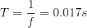
And the horizontal domain is 5 ms/div x 8div = 0.04s, so 2.4 periods will appear on screen
Add Answer to:
The oscilloscope display below is connected to a sine wave of 100 Hz frequency and 4...
Sine wave measurement: Images 6.9 – 6.12 show a sine wave. Note that Image 6.9 is...
 Sine wave measurement:
Images 6.9 – 6.12 show a sine wave. Note that Image 6.9 is a
close up of the function generator’s frequency display.
Using images 6.10 – 6.12, determine the amplitude of the sine
wave. Be sure to include proper units:
# of vertical divisions
VOLT/DIV
Amplitude
Determine the period and calculate the frequency:
# of horizontal divisions
TIME/DIV
Period
Frequency
Assuming that the frequency displayed in Image 6.9 is more
accurate than the oscilloscope, what is the...
Sine wave measurement:
Images 6.9 – 6.12 show a sine wave. Note that Image 6.9 is a
close up of the function generator’s frequency display.
Using images 6.10 – 6.12, determine the amplitude of the sine
wave. Be sure to include proper units:
# of vertical divisions
VOLT/DIV
Amplitude
Determine the period and calculate the frequency:
# of horizontal divisions
TIME/DIV
Period
Frequency
Assuming that the frequency displayed in Image 6.9 is more
accurate than the oscilloscope, what is the...
A sine wave signal is displayed on the screen of an oscilloscope. 6 peak-to-peak divisions are...
A sine wave signal is displayed on the screen of an oscilloscope. 6 peak-to-peak divisions are measured vertically and 8 peak-to-peak divisions horizontally. The voltage control is on the 1 volts / div scale and the sweep control is on the 4 ms scale. The frequency of the signal is: a.31.3 Hz b.23.3 Hz c.33.3 Hz d.43.3 Hz
A signal coming into the oscilloscope is a sine wave. Amplitude = 2 V, DC Offset...
A signal coming into the oscilloscope is a sine wave. Amplitude = 2 V, DC Offset = -1 V, Frequency = 10 Hz. Sketch the oscilloscope display. Select appropriate horizontal and vertical scales and note on the sketch. Label axes appropriately and indicate the 0V level on the sketch.
For the signal below shown on the oscilloscope: 1. What is the frequency in Hz? 2....
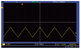 For the signal below shown on the oscilloscope:
1. What is the frequency in Hz?
2. If a DMM was measuring the signal and is set to DC Voltage,
what would the value be in Volts?
Triad M Pos: 2.400ms w w 1.00V M 1.00ms Ch1 / -5.20V 500.007Hz Jul 29, 2020, 21:31
For the signal below shown on the oscilloscope:
1. What is the frequency in Hz?
2. If a DMM was measuring the signal and is set to DC Voltage,
what would the value be in Volts?
Triad M Pos: 2.400ms w w 1.00V M 1.00ms Ch1 / -5.20V 500.007Hz Jul 29, 2020, 21:31
Draw the correct waveforms in the aranhs below for questions 10: 8. With the oscilloscope AC...
 Draw the correct waveforms in the aranhs below for questions 10: 8. With the oscilloscope AC coupled, draw the signal display you would expect to see on the screen of the oscilloscope on the graph provided below. SWITCH SETTINGS TIME/DIV 50 us VOLTS/DIV → 2 V SIGNAL PARAMETERS TH 12 Vdc 9. With the oscilloscope DC coupled, draw the signal display you would expect to see on the screen of the oscilloscope on the graph provided below. SWITCH SETTINGS TIME/DIV...
Analog Oscilloscope Setup: 1. Turn on the power to the oscilloscope. 2. Connect the function gene...
 Analog Oscilloscope Setup: 1. Turn on the power to the oscilloscope. 2. Connect the function generator to the Channel 1 input on the oscilloscope 3. In the Vertical Control Group, set the Channel 1 AC/GND/DC switch to AC. 4. Set the Volts-per-Division knob 5. Intensity knob: adjust the signal intensity and focus to a comfortable level by using the intensity and focus knobs, respectively Set the seconds-per-division knob 6. Assignment Procedures: 1. Using the settings completed above, answer the following...
A sine wave signal is displayed on the screen of an oscilloscope. 6 peak-to-peak divisions are...
A sine wave signal is displayed on the screen of an oscilloscope. 6 peak-to-peak divisions are measured vertically and 8 peak-to-peak divisions horizontally. The voltage control is on the 2 volts / div scale and the sweep control is on the 5ms scale. The signal period is: a. 0.03 seconds b. 0.04 seconds c. 4 seconds d. 0.005 seconds
*USE Multisim( Provide Pictures of work on Multisim for each step) and Fill the Tables Below...
 *USE Multisim( Provide Pictures of work on Multisim for each
step) and Fill the Tables Below
PROCEDURE: Review the front panel controls in each of the major groups. Then turn on the oscilloscope, select Chl, set the SEC/DIV to 0.1 ms/div, select AUTO triggering, and obtain a line across the face of the CRT. Although many of the measurements described in this experiment are automated in newer scopes, it is useful to learn to make these measurements manually. Turn on...
*USE Multisim( Provide Pictures of work on Multisim for each
step) and Fill the Tables Below
PROCEDURE: Review the front panel controls in each of the major groups. Then turn on the oscilloscope, select Chl, set the SEC/DIV to 0.1 ms/div, select AUTO triggering, and obtain a line across the face of the CRT. Although many of the measurements described in this experiment are automated in newer scopes, it is useful to learn to make these measurements manually. Turn on...
1.) You want to send a "square wave" pulse signal at a frequency of 60 Hz....
 1.) You want to send a "square wave" pulse signal at a frequency
of 60 Hz. What characteristics would this signal have?
2.) You want to set up a flicker fusion stimulus with a duty
cycle of 50%. Lets say you want to set up a stimulus that is a
total of 2 seconds long with a frequency of 1 Hz, 10 Hz, 20 Hz, 40
Hz, 60 Hz, 80 Hz, and 100 Hz. How do you do that? What...
1.) You want to send a "square wave" pulse signal at a frequency
of 60 Hz. What characteristics would this signal have?
2.) You want to set up a flicker fusion stimulus with a duty
cycle of 50%. Lets say you want to set up a stimulus that is a
total of 2 seconds long with a frequency of 1 Hz, 10 Hz, 20 Hz, 40
Hz, 60 Hz, 80 Hz, and 100 Hz. How do you do that? What...
Assume we have converted an analog sine wave signal of frequancy equals to 250 hz and amplitude e...
assume we have converted an analog sine wave signal of frequancy equals to 250 hz and amplitude equals to 4 volts into a PCM digital signal of zeros and ones . consider that one period of the anloge sine wave can be represented by 18 samples after sampling process ,whereas the number of quantization level is 32 show all the drawing and calculate the and calculate the time duration of the analog sine wave signal
 Sine wave measurement:
Images 6.9 – 6.12 show a sine wave. Note that Image 6.9 is a
close up of the function generator’s frequency display.
Using images 6.10 – 6.12, determine the amplitude of the sine
wave. Be sure to include proper units:
# of vertical divisions
VOLT/DIV
Amplitude
Determine the period and calculate the frequency:
# of horizontal divisions
TIME/DIV
Period
Frequency
Assuming that the frequency displayed in Image 6.9 is more
accurate than the oscilloscope, what is the...
Sine wave measurement:
Images 6.9 – 6.12 show a sine wave. Note that Image 6.9 is a
close up of the function generator’s frequency display.
Using images 6.10 – 6.12, determine the amplitude of the sine
wave. Be sure to include proper units:
# of vertical divisions
VOLT/DIV
Amplitude
Determine the period and calculate the frequency:
# of horizontal divisions
TIME/DIV
Period
Frequency
Assuming that the frequency displayed in Image 6.9 is more
accurate than the oscilloscope, what is the...
 For the signal below shown on the oscilloscope:
1. What is the frequency in Hz?
2. If a DMM was measuring the signal and is set to DC Voltage,
what would the value be in Volts?
Triad M Pos: 2.400ms w w 1.00V M 1.00ms Ch1 / -5.20V 500.007Hz Jul 29, 2020, 21:31
For the signal below shown on the oscilloscope:
1. What is the frequency in Hz?
2. If a DMM was measuring the signal and is set to DC Voltage,
what would the value be in Volts?
Triad M Pos: 2.400ms w w 1.00V M 1.00ms Ch1 / -5.20V 500.007Hz Jul 29, 2020, 21:31
 Draw the correct waveforms in the aranhs below for questions 10: 8. With the oscilloscope AC coupled, draw the signal display you would expect to see on the screen of the oscilloscope on the graph provided below. SWITCH SETTINGS TIME/DIV 50 us VOLTS/DIV → 2 V SIGNAL PARAMETERS TH 12 Vdc 9. With the oscilloscope DC coupled, draw the signal display you would expect to see on the screen of the oscilloscope on the graph provided below. SWITCH SETTINGS TIME/DIV...
 Analog Oscilloscope Setup: 1. Turn on the power to the oscilloscope. 2. Connect the function generator to the Channel 1 input on the oscilloscope 3. In the Vertical Control Group, set the Channel 1 AC/GND/DC switch to AC. 4. Set the Volts-per-Division knob 5. Intensity knob: adjust the signal intensity and focus to a comfortable level by using the intensity and focus knobs, respectively Set the seconds-per-division knob 6. Assignment Procedures: 1. Using the settings completed above, answer the following...
 *USE Multisim( Provide Pictures of work on Multisim for each
step) and Fill the Tables Below
PROCEDURE: Review the front panel controls in each of the major groups. Then turn on the oscilloscope, select Chl, set the SEC/DIV to 0.1 ms/div, select AUTO triggering, and obtain a line across the face of the CRT. Although many of the measurements described in this experiment are automated in newer scopes, it is useful to learn to make these measurements manually. Turn on...
*USE Multisim( Provide Pictures of work on Multisim for each
step) and Fill the Tables Below
PROCEDURE: Review the front panel controls in each of the major groups. Then turn on the oscilloscope, select Chl, set the SEC/DIV to 0.1 ms/div, select AUTO triggering, and obtain a line across the face of the CRT. Although many of the measurements described in this experiment are automated in newer scopes, it is useful to learn to make these measurements manually. Turn on...
 1.) You want to send a "square wave" pulse signal at a frequency
of 60 Hz. What characteristics would this signal have?
2.) You want to set up a flicker fusion stimulus with a duty
cycle of 50%. Lets say you want to set up a stimulus that is a
total of 2 seconds long with a frequency of 1 Hz, 10 Hz, 20 Hz, 40
Hz, 60 Hz, 80 Hz, and 100 Hz. How do you do that? What...
1.) You want to send a "square wave" pulse signal at a frequency
of 60 Hz. What characteristics would this signal have?
2.) You want to set up a flicker fusion stimulus with a duty
cycle of 50%. Lets say you want to set up a stimulus that is a
total of 2 seconds long with a frequency of 1 Hz, 10 Hz, 20 Hz, 40
Hz, 60 Hz, 80 Hz, and 100 Hz. How do you do that? What...
Most questions answered within 3 hours.
-
Where is the error in this code sequence?
String s1 = "Hello";
String s2 = "ello";...
asked 11 months ago -
Financial data for Joel de Paris, Inc., for last year
follow:
Joel de Paris, Inc.
Balance...
asked 11 months ago -
Consider this reaction:
Al2(SO4)3 (aq)+ BaCl3
(aq) Al2Cl6 (aq)- +
3BaSO4(s) . What is the...
asked 11 months ago -
Suppose that Savneet is considering increasing her
recent random sample from 20 car rentals to 40...
asked 11 months ago -
Trucks arrive at an unloading terminal at an average rate of 120
per hour.
Trucks arrive...
asked 11 months ago -
Why are methanol and ethanol completely soluble in water while
octanol is not very little soluble....
asked 11 months ago -
A facilities manager at a university reads in a research report
that the mean amount of...
asked 11 months ago -
When the CuSO4 is rehydrated by adding water to the anhydrous
compound, is this an endothermic...
asked 11 months ago -
A ray of sunlight is passing from diamond into crown glass; the
angle of incidence is...
asked 11 months ago -
A block of mass 0.249 kg is placed on top of a light, vertical
spring of...
asked 11 months ago -
how do the kidneys compensate in the presences of acidosis
a) trigger hyperventilate
b) reserve acid...
asked 11 months ago -
Question 501 pts
The rental rate of capital to the firm increases. Which of the
following...
asked 11 months ago