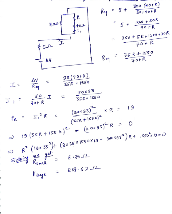
The resistor R in the figure below dissipates 19 W of power. Determine the value of...
The resistor R in the figure below dissipates 19 W of power. Determine the value of R. (Assume ΔV = 93 V.)
| R = | Ω | (larger value) |
| R = | Ω | (smaller value) |
A circuit begins at a battery labeled ΔV. Following the wire leaving upwards from the positive terminal, the wire passes through a resistor labeled 5.0 Ω. Then, the wire goes right before it splits into two vertical wires, creating two parallel branches. The left wire has a resistor labeled 30 Ω. The right wire has two resistors in series, one labeled 40 Ω above another labeled R. The two wires reconnect, and the single wire connects to the negative terminal of the battery.
Homework Answers
Add Answer to:
The resistor R in the figure below dissipates 19 W of
power. Determine the value of...
The resistor R in the figure below dissipates 12 W of power. Determine the value of...
 The resistor R in the figure below dissipates 12 W of
power. Determine the value of R. (Assume ΔV = 81
V.)
R =
Ω
(larger value)
R =
Ω
(smaller value)
ΑΛ 5.0 Ω ξ40 Ω -Δ' ξ30 Ω ER
The resistor R in the figure below dissipates 12 W of
power. Determine the value of R. (Assume ΔV = 81
V.)
R =
Ω
(larger value)
R =
Ω
(smaller value)
ΑΛ 5.0 Ω ξ40 Ω -Δ' ξ30 Ω ER
Consider the following figure. Note: The currents are not necessarily in the direction shown. (Assume R1...
Consider the following figure. Note: The currents are not necessarily in the direction shown. (Assume R1 = 31.0 Ω, R2 = 2.5 Ω, and V = 39 V.) A rectangular circuit begins at a battery on the bottom side labeled V with its positive terminal to the left of its negative terminal and extends leftward through resistor R2 with current I2 moving leftward. The circuit continues upward and then to the right on the top side where it splits into...
Electric Current and Circuits
 Transcipt: In the figure below, let R1 = 5.00 Ω, R2 = 8.00 Ω, and = 3.00 V.An open circuit begins at point a with a wire extending horizontally leftwards until it reaches a 4.00 V battery with the positive terminal on the left. After the battery, the wire splits into two branches. One branch continues left to a resistor R1, turns downwards and continues to a battery with emf ℰ with the positive terminal on top, and then turns...
Find the potential difference across each resistor in the figure below. (R1 = 5.40 Ω, R2...
Find the potential difference across each resistor in the figure below. (R1 = 5.40 Ω, R2 = 4.40 Ω, R3 = 3.20 Ω, R4 = 1.80 Ω) ΔVR1 = Incorrect: Your answer is incorrect. V ΔVR2 = V ΔVR3 = V ΔVR4 = V A circuit consists of two adjacent rectangular loops, one to the left of the other. All three vertical sides have a battery for which the positive terminal is above the negative terminal, as well as a...
Three 70.0-W, 130-V lightbulbs are connected across a ΔV = 130-V power source, as shown in...
 Three 70.0-W, 130-V lightbulbs are connected across a
ΔV = 130-V power source, as shown in the figure below.
Find the total power delivered to the three bulbs and the potential
difference across each. Assume the resistance of each bulb is
constant (even though, in reality, the resistance increases
markedly with current).
An open circuit begins at a terminal with a wire extending
horizontally rightwards until it reaches a lightbulb
R1. After the light bulb, the wire splits
downwards into...
Three 70.0-W, 130-V lightbulbs are connected across a
ΔV = 130-V power source, as shown in the figure below.
Find the total power delivered to the three bulbs and the potential
difference across each. Assume the resistance of each bulb is
constant (even though, in reality, the resistance increases
markedly with current).
An open circuit begins at a terminal with a wire extending
horizontally rightwards until it reaches a lightbulb
R1. After the light bulb, the wire splits
downwards into...
& w R R2 Each resistor has a resistance of 2.5 Ohms. The power supply voltage...
 & w R R2 Each resistor has a resistance of 2.5 Ohms. The power supply voltage is 12 V. If the wire connected to the negative terminal of the power supply has a voltage of ov, then what is the voltage of the wire which is connecting the two resistors (the middle wire)? O 6V 4.8V O 30 V O correct answer not shown O 12V
In the circuit of the figure below, the current I1 is 2.4 A and the values...
In the circuit of the figure below, the current I1 is 2.4 A and the values of e m f and R are unknown. What are the currents I2 and I3? (Enter the magnitude only.) I2 = I3 = A circuit is comprised of two adjacent square loops that share a side such that the right side of the left loop is also the left side of the right loop. The two loops meet at point a at the top...
*Chapter 27, Problem 012 The figure shows a resistor of resistance R = 6.00 Ω connected...
 *Chapter 27, Problem 012 The figure shows a resistor of resistance R = 6.00 Ω connected to an ideal battery of emf E = 15.2 V by means of two copper wires. Each wire has length 21.7 cm and radius 1.80 mm. In dealing with such circuits in this chapter, we generally neglect the potential differences along the wires and the transfer of energy to thermal energy in them. Check the validity of this neglect for the circuit of the...
The figure below shows an AC source, a transformer with a turns ratio of N1/N2 =...
 The figure below shows an AC source, a transformer with a turns
ratio of
N1/N2 =
2.40, a source resistor RS,and a load
resistor RL.
A circuit contains an AC source, two resistors, and a
transformer composed of two coils. The transformer will bridge two
halves of an otherwise disjoint circuit. The left half of the
circuit starts on the left at the AC source labeled
ΔVS, goes up and to the right to a resistor
labeled RS, goes down...
The figure below shows an AC source, a transformer with a turns
ratio of
N1/N2 =
2.40, a source resistor RS,and a load
resistor RL.
A circuit contains an AC source, two resistors, and a
transformer composed of two coils. The transformer will bridge two
halves of an otherwise disjoint circuit. The left half of the
circuit starts on the left at the AC source labeled
ΔVS, goes up and to the right to a resistor
labeled RS, goes down...
In the figure below, let R = 7.00 Ω, L = 2.50 mH, and C =...
 In the figure below, let R = 7.00 Ω, L = 2.50
mH, and C = 1.75 µF.
The circuit is a rectangular loop with a vertical wire in the
middle that extends from the bottom side of the loop to almost
reach the top side, ending at point b below the top side.
The left side contains a battery of emf ℰ with the
positive terminal above the negative terminal. The right side
contains a capacitor C. The top...
In the figure below, let R = 7.00 Ω, L = 2.50
mH, and C = 1.75 µF.
The circuit is a rectangular loop with a vertical wire in the
middle that extends from the bottom side of the loop to almost
reach the top side, ending at point b below the top side.
The left side contains a battery of emf ℰ with the
positive terminal above the negative terminal. The right side
contains a capacitor C. The top...
 The resistor R in the figure below dissipates 12 W of
power. Determine the value of R. (Assume ΔV = 81
V.)
R =
Ω
(larger value)
R =
Ω
(smaller value)
ΑΛ 5.0 Ω ξ40 Ω -Δ' ξ30 Ω ER
The resistor R in the figure below dissipates 12 W of
power. Determine the value of R. (Assume ΔV = 81
V.)
R =
Ω
(larger value)
R =
Ω
(smaller value)
ΑΛ 5.0 Ω ξ40 Ω -Δ' ξ30 Ω ER
 Three 70.0-W, 130-V lightbulbs are connected across a
ΔV = 130-V power source, as shown in the figure below.
Find the total power delivered to the three bulbs and the potential
difference across each. Assume the resistance of each bulb is
constant (even though, in reality, the resistance increases
markedly with current).
An open circuit begins at a terminal with a wire extending
horizontally rightwards until it reaches a lightbulb
R1. After the light bulb, the wire splits
downwards into...
Three 70.0-W, 130-V lightbulbs are connected across a
ΔV = 130-V power source, as shown in the figure below.
Find the total power delivered to the three bulbs and the potential
difference across each. Assume the resistance of each bulb is
constant (even though, in reality, the resistance increases
markedly with current).
An open circuit begins at a terminal with a wire extending
horizontally rightwards until it reaches a lightbulb
R1. After the light bulb, the wire splits
downwards into...
 & w R R2 Each resistor has a resistance of 2.5 Ohms. The power supply voltage is 12 V. If the wire connected to the negative terminal of the power supply has a voltage of ov, then what is the voltage of the wire which is connecting the two resistors (the middle wire)? O 6V 4.8V O 30 V O correct answer not shown O 12V
 *Chapter 27, Problem 012 The figure shows a resistor of resistance R = 6.00 Ω connected to an ideal battery of emf E = 15.2 V by means of two copper wires. Each wire has length 21.7 cm and radius 1.80 mm. In dealing with such circuits in this chapter, we generally neglect the potential differences along the wires and the transfer of energy to thermal energy in them. Check the validity of this neglect for the circuit of the...
 The figure below shows an AC source, a transformer with a turns
ratio of
N1/N2 =
2.40, a source resistor RS,and a load
resistor RL.
A circuit contains an AC source, two resistors, and a
transformer composed of two coils. The transformer will bridge two
halves of an otherwise disjoint circuit. The left half of the
circuit starts on the left at the AC source labeled
ΔVS, goes up and to the right to a resistor
labeled RS, goes down...
The figure below shows an AC source, a transformer with a turns
ratio of
N1/N2 =
2.40, a source resistor RS,and a load
resistor RL.
A circuit contains an AC source, two resistors, and a
transformer composed of two coils. The transformer will bridge two
halves of an otherwise disjoint circuit. The left half of the
circuit starts on the left at the AC source labeled
ΔVS, goes up and to the right to a resistor
labeled RS, goes down...
 In the figure below, let R = 7.00 Ω, L = 2.50
mH, and C = 1.75 µF.
The circuit is a rectangular loop with a vertical wire in the
middle that extends from the bottom side of the loop to almost
reach the top side, ending at point b below the top side.
The left side contains a battery of emf ℰ with the
positive terminal above the negative terminal. The right side
contains a capacitor C. The top...
In the figure below, let R = 7.00 Ω, L = 2.50
mH, and C = 1.75 µF.
The circuit is a rectangular loop with a vertical wire in the
middle that extends from the bottom side of the loop to almost
reach the top side, ending at point b below the top side.
The left side contains a battery of emf ℰ with the
positive terminal above the negative terminal. The right side
contains a capacitor C. The top...
Most questions answered within 3 hours.
-
Where is the error in this code sequence?
String s1 = "Hello";
String s2 = "ello";...
asked 11 months ago -
Financial data for Joel de Paris, Inc., for last year
follow:
Joel de Paris, Inc.
Balance...
asked 11 months ago -
Consider this reaction:
Al2(SO4)3 (aq)+ BaCl3
(aq) Al2Cl6 (aq)- +
3BaSO4(s) . What is the...
asked 11 months ago -
Suppose that Savneet is considering increasing her
recent random sample from 20 car rentals to 40...
asked 11 months ago -
Trucks arrive at an unloading terminal at an average rate of 120
per hour.
Trucks arrive...
asked 11 months ago -
Why are methanol and ethanol completely soluble in water while
octanol is not very little soluble....
asked 11 months ago -
A facilities manager at a university reads in a research report
that the mean amount of...
asked 11 months ago -
When the CuSO4 is rehydrated by adding water to the anhydrous
compound, is this an endothermic...
asked 11 months ago -
A ray of sunlight is passing from diamond into crown glass; the
angle of incidence is...
asked 11 months ago -
A block of mass 0.249 kg is placed on top of a light, vertical
spring of...
asked 11 months ago -
how do the kidneys compensate in the presences of acidosis
a) trigger hyperventilate
b) reserve acid...
asked 11 months ago -
Question 501 pts
The rental rate of capital to the firm increases. Which of the
following...
asked 11 months ago