
Homework Answers


Add Answer to:
Problem 3 A 50-Hz transformer is operated from a 60 Hz supply. Assume that the load...
Problem (1): A 15-KVA, 2400:240-V, 60 Hz transformer has the following equivalent circuit parameters: R =...
 Problem (1): A 15-KVA, 2400:240-V, 60 Hz transformer has the following equivalent circuit parameters: R = 2.522 R2 = 0.02522 Xi = 722 X = 0.0712 Re = 32 kl Xm = 11.5 k12 If the transformer is supplying a 10-kW, 0.8 PF lagging load at rated voltage, assuming the output voltage is the reference, draw the transformer's exact equivalent circuit referred to the primary (H.V) side and use it to calculate: 1. The input current 2. The input voltage...
1) A single-phase 50-kVA, 2400/240 volt, 60 Hz distribution transformer is used as a step-down tr...
 1) A single-phase 50-kVA, 2400/240 volt, 60 Hz distribution transformer is used as a step-down transformer at the load end of a 2400-volt feeder whose series impedance is (1.0+2.0) Ω. The equivalent series impedance of the transformer is (10+j25) Ω referred to the high voltage (primary) side. The transformer is delivering rated load at 0.8 power factor lagging and at rated secondary volitage. Neglect the transformer exciting curent. Using the transtormer raltings as base quantities work this problem in per...
A single-phase 100-kVA, 2400/240-volt, 60-Hz distribution transformer is used as a step-down transformer. The load, which...
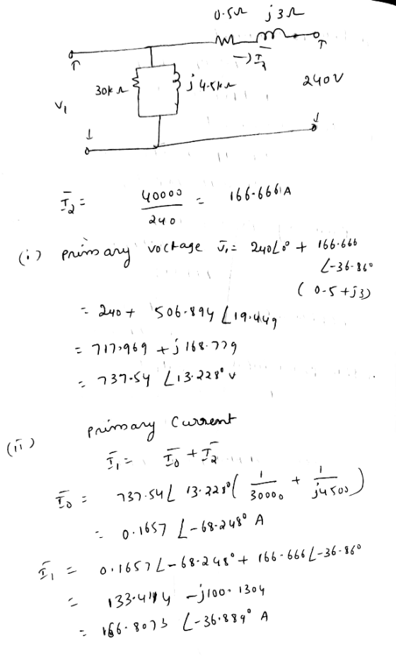
 A single-phase 100-kVA, 2400/240-volt, 60-Hz distribution transformer is used as a step-down transformer. The load, which is connected to the 240-volt secondary winding, absorbs 80 kVA at 0.8 power factor lagging and is at 230 volts. Assuming an ideal transformer, calculate the following: a) primary voltage. b) load impedance. c) load impedance referred to the primary. d) the real and reactive power supplied to the primary winding
3.4 A single-phase 100-kVA, 2400/240-volt, 60-Hz distribution transformer is used as a step-down transformer. The load,...
3.4 A single-phase 100-kVA, 2400/240-volt, 60-Hz distribution transformer is used as a step-down transformer. The load, which is connected to the 240-volt secondary wind- ing, absorbs 80 kVA at 0.8 power factor lagging and is at 230 volts. Assuming an ideal transformer, calculate the following: (a) primary voltage, (b) load impedance, (c) load impedance referred to the primary, and (d) the real and reactive power sup- plied to the primary winding.
Choose the base power as 50-KVA, the primary base voltage as 2400-V, the secondary voltage as...
 Choose the base power as 50-KVA, the primary base voltage as 2400-V, the secondary voltage as 240-V: (a) Calculate and sketch the transformer equivalent circuit in per unit values' (b) The transformer is carrying rate load of 1.0 pu at.8 power factor lagging. Calculate the primary voltage in per unit. (c) Calculate the efficiency of the transformer at this load. A 50-KVA 2400/240-V, 60-Hz distribution transformer is tested with the following results: Open circuit Test Short Circuit Test Voc =...
A 20 kVA, 60 Hz, 2400/240 V single-phase distribution transformer has been tested to determine its...
A 20 kVA, 60 Hz, 2400/240 V single-phase distribution transformer has been tested to determine its equivalent circuit. The results of the test are shown below: Open circuit Test (on low voltage side) Voc=240V, Ioc=1.028A, Poc=122W. Short circuit test (On high voltage side) Vsc=61.3V, Isc=8.33A, Psc=257W. The transformer is supplying power to a load that draws 15 kVA at 240 V. The load power factor is 0.90 lagging. Calculate the voltage regulation for this operation condition.
4. The figure below shows the equivalent circuit of a 2400/240-V, 60-Hz transformer. The high-side leakage...
 4. The figure below shows the equivalent circuit of a 2400/240-V, 60-Hz transformer. The high-side leakage impedance is (1.2+j 2.0) 2. the low-side leakage impedance is (0.012 ti 0.02) S2, and Xm at the high-side is 1800 2. Neglect the Hysteresis and Eddy current loss resistance Rhe Calculate the input voltage if the output voltage is 240 V (rms). Given the load resistance is 1.5 12 and the power factor is 0.8 (lagging). ཉིས་པ་དེ། དེ་ | ༼ ། ༼། །
The short-circuit test readings for a 50-kVA 2400:240-V transformer are 48 V, 20.8 A, and 617...
 The short-circuit test readings for a 50-kVA 2400:240-V transformer are 48 V, 20.8 A, and 617 W, with the instruments located on the high-voltage side and the low-voltage side short- circuited. An open-circuit test with the low-voltage side energized gives instrument readings on that side of 240 V, 5.41 A, and 186 W. 1. Calculate the equivalent parameters of the transformer as referred to the high-voltage side. 2. Draw the equivalent approximate circuit of that transformer referred to the high...
A 200 kVA, 7200/600 V, 60 Hz transformer is operating at rated load and 0.9 p.f....
 A 200 kVA, 7200/600 V, 60 Hz transformer is operating at rated
load and 0.9 p.f. lagging. The core loss, winding resistances and
leakage reactances, expressed in per unit are 0.0056, 0.0133 and
0.0557 respectively. Determine: a) The efficiency. b) The voltage
regulation. c) The efficiency and regulation at 0.3 load and 0.8
p.f. lagging.
A 200 kVA, 7200/600 V, 60 Hz transformer is operating at rated load and 0.9 p.f. lagging. The core loss, winding resistances and leakage reactances,...
A 200 kVA, 7200/600 V, 60 Hz transformer is operating at rated
load and 0.9 p.f. lagging. The core loss, winding resistances and
leakage reactances, expressed in per unit are 0.0056, 0.0133 and
0.0557 respectively. Determine: a) The efficiency. b) The voltage
regulation. c) The efficiency and regulation at 0.3 load and 0.8
p.f. lagging.
A 200 kVA, 7200/600 V, 60 Hz transformer is operating at rated load and 0.9 p.f. lagging. The core loss, winding resistances and leakage reactances,...
A three phase 250 kVA 2400:415 V 50 Hz distribution transformer is constructed by connecting thre...
 A three phase 250 kVA 2400:415 V 50 Hz distribution transformer is constructed by connecting three single phase transformers in the Dynll vector group as shown in Fig.P1. The per phase equivalent circuit parameters on the high voltage side are: R1-0.72 Ω, Xi,-0.92 Ω, R2-0.70 Ω, Xp-0.90 Ω, R.-308.49 Ω, and X,,-44.61 Ω (a) Sketch the corresponding phasor diagram of the primary and secondary voltages for the Dynll vector group; lagging; terminal voltage is 415 V line to line, and...
 Problem (1): A 15-KVA, 2400:240-V, 60 Hz transformer has the following equivalent circuit parameters: R = 2.522 R2 = 0.02522 Xi = 722 X = 0.0712 Re = 32 kl Xm = 11.5 k12 If the transformer is supplying a 10-kW, 0.8 PF lagging load at rated voltage, assuming the output voltage is the reference, draw the transformer's exact equivalent circuit referred to the primary (H.V) side and use it to calculate: 1. The input current 2. The input voltage...
 1) A single-phase 50-kVA, 2400/240 volt, 60 Hz distribution transformer is used as a step-down transformer at the load end of a 2400-volt feeder whose series impedance is (1.0+2.0) Ω. The equivalent series impedance of the transformer is (10+j25) Ω referred to the high voltage (primary) side. The transformer is delivering rated load at 0.8 power factor lagging and at rated secondary volitage. Neglect the transformer exciting curent. Using the transtormer raltings as base quantities work this problem in per...
 A single-phase 100-kVA, 2400/240-volt, 60-Hz distribution transformer is used as a step-down transformer. The load, which is connected to the 240-volt secondary winding, absorbs 80 kVA at 0.8 power factor lagging and is at 230 volts. Assuming an ideal transformer, calculate the following: a) primary voltage. b) load impedance. c) load impedance referred to the primary. d) the real and reactive power supplied to the primary winding
 Choose the base power as 50-KVA, the primary base voltage as 2400-V, the secondary voltage as 240-V: (a) Calculate and sketch the transformer equivalent circuit in per unit values' (b) The transformer is carrying rate load of 1.0 pu at.8 power factor lagging. Calculate the primary voltage in per unit. (c) Calculate the efficiency of the transformer at this load. A 50-KVA 2400/240-V, 60-Hz distribution transformer is tested with the following results: Open circuit Test Short Circuit Test Voc =...
 4. The figure below shows the equivalent circuit of a 2400/240-V, 60-Hz transformer. The high-side leakage impedance is (1.2+j 2.0) 2. the low-side leakage impedance is (0.012 ti 0.02) S2, and Xm at the high-side is 1800 2. Neglect the Hysteresis and Eddy current loss resistance Rhe Calculate the input voltage if the output voltage is 240 V (rms). Given the load resistance is 1.5 12 and the power factor is 0.8 (lagging). ཉིས་པ་དེ། དེ་ | ༼ ། ༼། །
 The short-circuit test readings for a 50-kVA 2400:240-V transformer are 48 V, 20.8 A, and 617 W, with the instruments located on the high-voltage side and the low-voltage side short- circuited. An open-circuit test with the low-voltage side energized gives instrument readings on that side of 240 V, 5.41 A, and 186 W. 1. Calculate the equivalent parameters of the transformer as referred to the high-voltage side. 2. Draw the equivalent approximate circuit of that transformer referred to the high...
 A 200 kVA, 7200/600 V, 60 Hz transformer is operating at rated
load and 0.9 p.f. lagging. The core loss, winding resistances and
leakage reactances, expressed in per unit are 0.0056, 0.0133 and
0.0557 respectively. Determine: a) The efficiency. b) The voltage
regulation. c) The efficiency and regulation at 0.3 load and 0.8
p.f. lagging.
A 200 kVA, 7200/600 V, 60 Hz transformer is operating at rated load and 0.9 p.f. lagging. The core loss, winding resistances and leakage reactances,...
A 200 kVA, 7200/600 V, 60 Hz transformer is operating at rated
load and 0.9 p.f. lagging. The core loss, winding resistances and
leakage reactances, expressed in per unit are 0.0056, 0.0133 and
0.0557 respectively. Determine: a) The efficiency. b) The voltage
regulation. c) The efficiency and regulation at 0.3 load and 0.8
p.f. lagging.
A 200 kVA, 7200/600 V, 60 Hz transformer is operating at rated load and 0.9 p.f. lagging. The core loss, winding resistances and leakage reactances,...
 A three phase 250 kVA 2400:415 V 50 Hz distribution transformer is constructed by connecting three single phase transformers in the Dynll vector group as shown in Fig.P1. The per phase equivalent circuit parameters on the high voltage side are: R1-0.72 Ω, Xi,-0.92 Ω, R2-0.70 Ω, Xp-0.90 Ω, R.-308.49 Ω, and X,,-44.61 Ω (a) Sketch the corresponding phasor diagram of the primary and secondary voltages for the Dynll vector group; lagging; terminal voltage is 415 V line to line, and...
Most questions answered within 3 hours.
-
Where is the error in this code sequence?
String s1 = "Hello";
String s2 = "ello";...
asked 10 months ago -
Financial data for Joel de Paris, Inc., for last year
follow:
Joel de Paris, Inc.
Balance...
asked 10 months ago -
Consider this reaction:
Al2(SO4)3 (aq)+ BaCl3
(aq) Al2Cl6 (aq)- +
3BaSO4(s) . What is the...
asked 10 months ago -
Suppose that Savneet is considering increasing her
recent random sample from 20 car rentals to 40...
asked 10 months ago -
Trucks arrive at an unloading terminal at an average rate of 120
per hour.
Trucks arrive...
asked 10 months ago -
Why are methanol and ethanol completely soluble in water while
octanol is not very little soluble....
asked 10 months ago -
A facilities manager at a university reads in a research report
that the mean amount of...
asked 10 months ago -
When the CuSO4 is rehydrated by adding water to the anhydrous
compound, is this an endothermic...
asked 10 months ago -
A ray of sunlight is passing from diamond into crown glass; the
angle of incidence is...
asked 10 months ago -
A block of mass 0.249 kg is placed on top of a light, vertical
spring of...
asked 10 months ago -
how do the kidneys compensate in the presences of acidosis
a) trigger hyperventilate
b) reserve acid...
asked 10 months ago -
Question 501 pts
The rental rate of capital to the firm increases. Which of the
following...
asked 10 months ago