
Homework Answers
Given
Apparent Power delivered to the load S = 3 MW +j2 MVAR = 3.606 ∠33.69 MVA
Line current is 288, lets assume it as reference phasor Iline = 288 ∠0 Amp. This will be same for source and line since all are connected in series
We know
S = Vsource Iline*
Then load voltage is Vsource = S / Iline* = 3.606 ∠33.69 * 106/288 ∠0 = 12.519 kV ∠ 33.69
The source voltage leads the current by 33.69 degrees hence the power factor is cos(33.69) = 0.832 lagging
And load voltage is Vload = Vsource - Iline Zline = 12.519 kV ∠33.69 - 288∠0 x (2.4+j15) /1000 kV = 10.07 ∠15.1 kV
The load voltage leads the current by 15.1 degrees hence the power factor is cos(15.1) = 0.965 lagging
The load power can be thus calculated by
Sload = Vload Iline*
==> Sload = 10.07 ∠15.1 kV x 288∠0 = 2.9 ∠15.1 MVA = 2.8 MW + j 0.755 MVAR
Line power calculations:
Vline = I (R+jX) = 288 (2.4+j15) = 4.375 ∠80.9 kV
Pline = I2 R = 2882 x 2.4 = 199.065 kW
Qline = I2 X = 2882 x 15 = 1244.160 kVAR
Sline = 1260.27 ∠80.9 kVA = 1.26∠80.9 MVA
pf = cos 80.9 lag = 0.158 lag
Hence the completed table is :
| S (MVA) | P(MW) | Q(MVAR) | Φ(deg) | pf(lead/lag) | V(kV) | I(A) | |
| Load | 2.9 | 2.8 | 0.755 | 15.1 | 0.965 lag | 10.07 | 288 |
| Line | 1.26 | 0.199 | 1.244 | 80.9 | 0.158 lag | 4.375 | 288 |
| Source | 3.606 | 3 | 2 | 33.69 | 0.832 lag | 12.519 | 288 |
Add Answer to:
RLine XLine AC Voltage Source Load Z Line = 2.4Ω + j 15Ω Fill in the...
Consider a single-phase circuit where a 14 kV, 60 Hz voltage source feeds an electric load...
 Consider a single-phase circuit where a 14 kV, 60 Hz voltage source feeds an electric load through a feeder whose impedance is 1.5 + j 3 Ω. The load is known to consume 4 MW and 3 MVAR. Let V and δ represent the rms voltage and its phase angle (relative to the source voltage) at the load terminals. Two equations are needed to solve for V and δ. 1) Derive two analytical expressions in terms of V and δ...
source + X mission line Resistance Resistive e Inductive Lead RS som i VST + R...
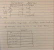 source + X mission line Resistance Resistive e Inductive Lead RS som i VST + R loch " L Load 5v Lo Speak) o - FIKH = ------- o calculate magnitude of voltage across load, va. o calculate values to fill in the table below. calculated I VA current (mA) PL (mW). QL (MVAR) sb (m VA) FR
3. For the system shown below, determine the following (a) the reflection coefficient at the load end (b) the reflection coefficient at the source end (c) the VSWR (d) the phasor voltage at the load...
 3. For the system shown below, determine the following (a) the reflection coefficient at the load end (b) the reflection coefficient at the source end (c) the VSWR (d) the phasor voltage at the load end of the line (e) the phasor voltage at the center of the line 7-7=15Ω 0
3. For the system shown below, determine the following (a) the reflection coefficient at the load end (b) the reflection coefficient at the source end (c) the VSWR (d)...
3. For the system shown below, determine the following (a) the reflection coefficient at the load end (b) the reflection coefficient at the source end (c) the VSWR (d) the phasor voltage at the load end of the line (e) the phasor voltage at the center of the line 7-7=15Ω 0
3. For the system shown below, determine the following (a) the reflection coefficient at the load end (b) the reflection coefficient at the source end (c) the VSWR (d)...
a. The value of the voltage source and all the load impedances of AC circuit in...
 a. The value of the voltage source and all the load impedances of AC circuit in Figure Q2(a) are given as list below; 21 Z3 V. Z2 ZA Figure Q2(a) Calculate the real and reactive power absorbed by load impedances and (C01: P01 - 8 marks) ii. Determine the power factor at the load impedance, (C01: P01 - 2 marks) a. The value of the voltage source and all the load impedances of AC circuit in Figure Q2(a) are given...
QUESTION 4: AC POWER - PF CORRECTION points) The voltage and current for a load Z...
 QUESTION 4: AC POWER - PF CORRECTION points) The voltage and current for a load Z are given by Vrms = 120290° and IRMS = 40230 Volts and Amps respectively; F-60 Hz. Do the following: • Determine the load Z6 • Determine the PF • State whether this is a leading/lagging PF. • Determine the Power delivered to the Load (Watts) • Sketch the power triangle and include all relevant information (quantities, units etc.) • What type of element must...
I. A balanced three-phase positive sequence wye-connected 60Hz source voltage has line-neutral voltage of V, 1000 V. It is connected to a three- phase wye connected load whose impedance is z 50+j...
 I. A balanced three-phase positive sequence wye-connected 60Hz source voltage has line-neutral voltage of V, 1000 V. It is connected to a three- phase wye connected load whose impedance is z 50+j37.7 2 a. Find line currents ia ib, ic and line-line voltages Vab, Vbo Vac b. Find the total complex power delivered to the load. c. Find delta-connected capacitor bank needed to bring the PF to 0.95 (lagging) of system. d. Re-calculate currents la, ib, io with Case c....
I. A balanced three-phase positive sequence wye-connected 60Hz source voltage has line-neutral voltage of V, 1000 V. It is connected to a three- phase wye connected load whose impedance is z 50+j...
 I. A balanced three-phase positive sequence wye-connected 60Hz source voltage has line-neutral voltage of V, 1000 V. It is connected to a three- phase wye connected load whose impedance is z 50+j37.7 2 a. Find line currents ia ib, ic and line-line voltages Vab, Vbo Vac b. Find the total complex power delivered to the load. c. Find delta-connected capacitor bank needed to bring the PF to 0.95 (lagging) of system. d. Re-calculate currents la, ib, io with Case c....
Problem 3: The line-to-neutral voltage at the terminals of the balanced three-phase load in the circuit...
 Problem 3: The line-to-neutral voltage at the terminals of the balanced three-phase load in the circuit shown in Fig. 3 is 1200V. At this voltage, the load is absorbing 500kVA at 0.96 pf lag. a) Use Van as the reference and express Ina in the polar form. b) Calculate the complex power associated with the ideal three-phase source. c) Check that the total average power delivered equals the total average power absorbed. d) Check that the total magnetizing reactive power...
A 60-Hz single-phase AC power network is shown in the figure below with four different loads. The source voltage ES-320 0. Prior to adding the capacitor load for power factor correction, the source c...
 A 60-Hz single-phase AC power network is shown in the figure below with four different loads. The source voltage ES-320 0. Prior to adding the capacitor load for power factor correction, the source current IS-135 30 . Determine the capacitance (in μF) of the capacitive load that will make the power factor unity (pf 1.0) of the system. Enter the one best answer (as a number without the units) from the following choices: Sync 74 % 6 15 kVA 10...
3. A system of two transmission lines connected in series are driven by a voltage source fi(t) Vo...
 3. A system of two transmission lines connected in series are driven by a voltage source fi(t) Vou(t) and terminated by a resistive load of 60S2 as shown in the figure below. A switch is closed at t 0 and the positive voltages are measured for 5 μs giving the bounce diagram shown in the figure-the voltage values indicated in the diagram correspond to delta function weights times the source voltage products such as VOTg, VOTg(1 +「2), etc. 400 m...
 Consider a single-phase circuit where a 14 kV, 60 Hz voltage source feeds an electric load through a feeder whose impedance is 1.5 + j 3 Ω. The load is known to consume 4 MW and 3 MVAR. Let V and δ represent the rms voltage and its phase angle (relative to the source voltage) at the load terminals. Two equations are needed to solve for V and δ. 1) Derive two analytical expressions in terms of V and δ...
 source + X mission line Resistance Resistive e Inductive Lead RS som i VST + R loch " L Load 5v Lo Speak) o - FIKH = ------- o calculate magnitude of voltage across load, va. o calculate values to fill in the table below. calculated I VA current (mA) PL (mW). QL (MVAR) sb (m VA) FR
 3. For the system shown below, determine the following (a) the reflection coefficient at the load end (b) the reflection coefficient at the source end (c) the VSWR (d) the phasor voltage at the load end of the line (e) the phasor voltage at the center of the line 7-7=15Ω 0
3. For the system shown below, determine the following (a) the reflection coefficient at the load end (b) the reflection coefficient at the source end (c) the VSWR (d)...
3. For the system shown below, determine the following (a) the reflection coefficient at the load end (b) the reflection coefficient at the source end (c) the VSWR (d) the phasor voltage at the load end of the line (e) the phasor voltage at the center of the line 7-7=15Ω 0
3. For the system shown below, determine the following (a) the reflection coefficient at the load end (b) the reflection coefficient at the source end (c) the VSWR (d)...
 a. The value of the voltage source and all the load impedances of AC circuit in Figure Q2(a) are given as list below; 21 Z3 V. Z2 ZA Figure Q2(a) Calculate the real and reactive power absorbed by load impedances and (C01: P01 - 8 marks) ii. Determine the power factor at the load impedance, (C01: P01 - 2 marks) a. The value of the voltage source and all the load impedances of AC circuit in Figure Q2(a) are given...
 QUESTION 4: AC POWER - PF CORRECTION points) The voltage and current for a load Z are given by Vrms = 120290° and IRMS = 40230 Volts and Amps respectively; F-60 Hz. Do the following: • Determine the load Z6 • Determine the PF • State whether this is a leading/lagging PF. • Determine the Power delivered to the Load (Watts) • Sketch the power triangle and include all relevant information (quantities, units etc.) • What type of element must...
 I. A balanced three-phase positive sequence wye-connected 60Hz source voltage has line-neutral voltage of V, 1000 V. It is connected to a three- phase wye connected load whose impedance is z 50+j37.7 2 a. Find line currents ia ib, ic and line-line voltages Vab, Vbo Vac b. Find the total complex power delivered to the load. c. Find delta-connected capacitor bank needed to bring the PF to 0.95 (lagging) of system. d. Re-calculate currents la, ib, io with Case c....
 I. A balanced three-phase positive sequence wye-connected 60Hz source voltage has line-neutral voltage of V, 1000 V. It is connected to a three- phase wye connected load whose impedance is z 50+j37.7 2 a. Find line currents ia ib, ic and line-line voltages Vab, Vbo Vac b. Find the total complex power delivered to the load. c. Find delta-connected capacitor bank needed to bring the PF to 0.95 (lagging) of system. d. Re-calculate currents la, ib, io with Case c....
 Problem 3: The line-to-neutral voltage at the terminals of the balanced three-phase load in the circuit shown in Fig. 3 is 1200V. At this voltage, the load is absorbing 500kVA at 0.96 pf lag. a) Use Van as the reference and express Ina in the polar form. b) Calculate the complex power associated with the ideal three-phase source. c) Check that the total average power delivered equals the total average power absorbed. d) Check that the total magnetizing reactive power...
 A 60-Hz single-phase AC power network is shown in the figure below with four different loads. The source voltage ES-320 0. Prior to adding the capacitor load for power factor correction, the source current IS-135 30 . Determine the capacitance (in μF) of the capacitive load that will make the power factor unity (pf 1.0) of the system. Enter the one best answer (as a number without the units) from the following choices: Sync 74 % 6 15 kVA 10...
 3. A system of two transmission lines connected in series are driven by a voltage source fi(t) Vou(t) and terminated by a resistive load of 60S2 as shown in the figure below. A switch is closed at t 0 and the positive voltages are measured for 5 μs giving the bounce diagram shown in the figure-the voltage values indicated in the diagram correspond to delta function weights times the source voltage products such as VOTg, VOTg(1 +「2), etc. 400 m...
Most questions answered within 3 hours.
-
Where is the error in this code sequence?
String s1 = "Hello";
String s2 = "ello";...
asked 11 months ago -
Financial data for Joel de Paris, Inc., for last year
follow:
Joel de Paris, Inc.
Balance...
asked 11 months ago -
Consider this reaction:
Al2(SO4)3 (aq)+ BaCl3
(aq) Al2Cl6 (aq)- +
3BaSO4(s) . What is the...
asked 11 months ago -
Suppose that Savneet is considering increasing her
recent random sample from 20 car rentals to 40...
asked 11 months ago -
Trucks arrive at an unloading terminal at an average rate of 120
per hour.
Trucks arrive...
asked 11 months ago -
Why are methanol and ethanol completely soluble in water while
octanol is not very little soluble....
asked 11 months ago -
A facilities manager at a university reads in a research report
that the mean amount of...
asked 11 months ago -
When the CuSO4 is rehydrated by adding water to the anhydrous
compound, is this an endothermic...
asked 11 months ago -
A ray of sunlight is passing from diamond into crown glass; the
angle of incidence is...
asked 11 months ago -
A block of mass 0.249 kg is placed on top of a light, vertical
spring of...
asked 11 months ago -
how do the kidneys compensate in the presences of acidosis
a) trigger hyperventilate
b) reserve acid...
asked 11 months ago -
Question 501 pts
The rental rate of capital to the firm increases. Which of the
following...
asked 11 months ago