

Homework Answers

![Applying KVL in the three loops we get (1) (R + Ver eo O L di te, e at H die Ħ (2) di = {le Llen - ez] i Re E. (3) Now applyi](http://img.homeworklib.com/questions/0c2dd790-3071-11eb-911d-ad2140b7ed21.png?x-oss-process=image/resize,w_560)


![dic at -R₂ L -/ tu L + dva dt LO 1 C2 ol Ive 3 (41) VE no [1]• [0][: eq](http://img.homeworklib.com/questions/1327b080-3071-11eb-bd07-ebd89525aa68.png?x-oss-process=image/resize,w_560)
Add Answer to:
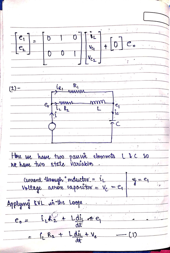
2. Design state space model of following systems: a) el is input and e2 is the...
Obtain the state-space model if R1-2 ?, R2 = 1 ? , C 0.25 F, and...
 Obtain the state-space model if R1-2 ?, R2 = 1 ? , C 0.25 F, and L = 0.2 H. Assume i, v, and voltage across capacitor C are state variables and output respectively vc =[0 1] 1.1 -4-2V2 Vc [0 1] vc =[0 1] d. Vc [0 1]
Question 5 Following differential equations defines input-output relationships of a system with y as output and...
 Question 5 Following differential equations defines input-output relationships of a system with y as output and r as inputs. d’yı + dy 2 + y, + 5 y, = 10 r, dt ? dt. dy 2 + 1 + 7y, = 8r2 dt dt at a) Define suitable state variables and find the state equation and output equation. [8marks] b) Find system matrix (A), input matrix (B) and output matrix (C). [5marks] c) Draw the state space diagram and find...
Problem 2: Transfer Functions of Mechanical Systems. (20 Points) A model sketch for a two-mass mechanical...
 Problem 2: Transfer Functions of Mechanical Systems. (20 Points) A model sketch for a two-mass mechanical system subjected to fluctuations (t) at the wall is provided in figure 2. Spring k, is interconnected with both spring ka and damper Os at the nodal point. The independent displacement of mass m is denoted by 1, the independent displacement of mass m, is denoted by r2, and the independent displacement of the node is denoted by ra. Assume a linear force-displacement/velocity relationship...
Use S-R flip-flops to design a 3-bit counter (C, B, A) with the repeating binary counting...
 Use S-R flip-flops to design a 3-bit counter (C, B, A) with the repeating binary counting sequence: 1, 3, 2, 6, 7, 5, 4. Show clearly the following: (a) The circuit's state table with the present-state entries in ascending order. Present State (t) Next State (t+1) Flip-flop Inputs с B A m с B A Sc Rc SB RE SA RA Required format of the state table in Problem 1(a). Show table grid lines and align all entries per column....
2. An effective control design concerns itself with more than the transfer function between the reference...
 2. An effective control design concerns itself with more than the transfer function between the reference input, r(t), and the system output, y(t). For well-posedness and eventually internal stability (see (DFT) Sections 3.1 and 3.2), all nine transfer functions between the input signals R[S], D[s], and N[s] and the outputs of the summing junctions e1[s], e2[S], and e3 [S], must exist and be stable, respectively. For this problem, find the following four transfer functions in terms of G1 [s], G2...
Problem 1. Use S-R flip-flops to design a 3-bit counter (C, B, A) with the repeating...
 Problem 1. Use S-R flip-flops to design a 3-bit counter (C, B, A) with the repeating binary counting sequence: 1, 3, 2, 6, 7, 5, 4. Show clearly the following: (a) The circuit's state table with the present-state entries in ascending order. 14 pts. Present State (t) Next State (t+1) Flip-flop Inputs с в А m C B A Sc Rc RE RA SB SA Required format of the state table in Problem 1(a). Show table grid lines and align...
Given the State Table Below 01* 02 03 1 203 X-1 0 000 01 0 0 0 1 0 0 A. Draw a state Diagram (5 points) B. Create the "design truth table" for the "next state" and the "output"...
 Given the State Table Below 01* 02 03 1 203 X-1 0 000 01 0 0 0 1 0 0 A. Draw a state Diagram (5 points) B. Create the "design truth table" for the "next state" and the "output" (5 points) C. Make a Karnaugh for each "next state" and the "output" (10 points) When making the Karnaugh maps, "xO1" should be along the top and "0203'" along the side (The two missing states should be considered "DONT CARES")...
Consider the following system: -1-2-21 гг 1 0 1 L Where u is the system input and y is the measur...
 control system with observer
Consider the following system: -1-2-21 гг 1 0 1 L Where u is the system input and y is the measured output. 1. Find the transfer function of the system. 2. Design a state feedback controller with a full-state observer such that the step response of the closed loop system is second order dominant with an overshoot Mp settling time ts s 5 sec. Represent the observer-based control system in a compact state space form. 10%...
control system with observer
Consider the following system: -1-2-21 гг 1 0 1 L Where u is the system input and y is the measured output. 1. Find the transfer function of the system. 2. Design a state feedback controller with a full-state observer such that the step response of the closed loop system is second order dominant with an overshoot Mp settling time ts s 5 sec. Represent the observer-based control system in a compact state space form. 10%...
3. For the non-ideal buck converter in Fig. 3, 1) Derive the state space model with state variable vector X as (it, vc), input variable vector U as (vi, io), output variable vector Y as vo. Deriv...
 3. For the non-ideal buck converter in Fig. 3, 1) Derive the state space model with state variable vector X as (it, vc), input variable vector U as (vi, io), output variable vector Y as vo. Derive the coefficient matrices in the model below. Note that duty cycle should be considered and included. dt ) di di dt 2)Select the line of a L, ie., a L-4-i, +A2Mz + Bı'y4B12%.and use perturbation-and- dt linearization approach to derive its small-signal representation....
Standard state-space representations of LTI systems x(t)-Ax(t)+Bu(t); yt)-Cx(t)+Du(f) Two different systems have the following representations: 0...
 Standard state-space representations of LTI systems x(t)-Ax(t)+Bu(t); yt)-Cx(t)+Du(f) Two different systems have the following representations: 0 2 -3 a. Determine the input-output transfer functions for the two systems above. Are they the same? b. Explain the result obtained in part a. c. Determine the poles and zeros of the two systems above
 Obtain the state-space model if R1-2 ?, R2 = 1 ? , C 0.25 F, and L = 0.2 H. Assume i, v, and voltage across capacitor C are state variables and output respectively vc =[0 1] 1.1 -4-2V2 Vc [0 1] vc =[0 1] d. Vc [0 1]
 Question 5 Following differential equations defines input-output relationships of a system with y as output and r as inputs. d’yı + dy 2 + y, + 5 y, = 10 r, dt ? dt. dy 2 + 1 + 7y, = 8r2 dt dt at a) Define suitable state variables and find the state equation and output equation. [8marks] b) Find system matrix (A), input matrix (B) and output matrix (C). [5marks] c) Draw the state space diagram and find...
 Problem 2: Transfer Functions of Mechanical Systems. (20 Points) A model sketch for a two-mass mechanical system subjected to fluctuations (t) at the wall is provided in figure 2. Spring k, is interconnected with both spring ka and damper Os at the nodal point. The independent displacement of mass m is denoted by 1, the independent displacement of mass m, is denoted by r2, and the independent displacement of the node is denoted by ra. Assume a linear force-displacement/velocity relationship...
 Use S-R flip-flops to design a 3-bit counter (C, B, A) with the repeating binary counting sequence: 1, 3, 2, 6, 7, 5, 4. Show clearly the following: (a) The circuit's state table with the present-state entries in ascending order. Present State (t) Next State (t+1) Flip-flop Inputs с B A m с B A Sc Rc SB RE SA RA Required format of the state table in Problem 1(a). Show table grid lines and align all entries per column....
 2. An effective control design concerns itself with more than the transfer function between the reference input, r(t), and the system output, y(t). For well-posedness and eventually internal stability (see (DFT) Sections 3.1 and 3.2), all nine transfer functions between the input signals R[S], D[s], and N[s] and the outputs of the summing junctions e1[s], e2[S], and e3 [S], must exist and be stable, respectively. For this problem, find the following four transfer functions in terms of G1 [s], G2...
 Problem 1. Use S-R flip-flops to design a 3-bit counter (C, B, A) with the repeating binary counting sequence: 1, 3, 2, 6, 7, 5, 4. Show clearly the following: (a) The circuit's state table with the present-state entries in ascending order. 14 pts. Present State (t) Next State (t+1) Flip-flop Inputs с в А m C B A Sc Rc RE RA SB SA Required format of the state table in Problem 1(a). Show table grid lines and align...
 Given the State Table Below 01* 02 03 1 203 X-1 0 000 01 0 0 0 1 0 0 A. Draw a state Diagram (5 points) B. Create the "design truth table" for the "next state" and the "output" (5 points) C. Make a Karnaugh for each "next state" and the "output" (10 points) When making the Karnaugh maps, "xO1" should be along the top and "0203'" along the side (The two missing states should be considered "DONT CARES")...
 control system with observer
Consider the following system: -1-2-21 гг 1 0 1 L Where u is the system input and y is the measured output. 1. Find the transfer function of the system. 2. Design a state feedback controller with a full-state observer such that the step response of the closed loop system is second order dominant with an overshoot Mp settling time ts s 5 sec. Represent the observer-based control system in a compact state space form. 10%...
control system with observer
Consider the following system: -1-2-21 гг 1 0 1 L Where u is the system input and y is the measured output. 1. Find the transfer function of the system. 2. Design a state feedback controller with a full-state observer such that the step response of the closed loop system is second order dominant with an overshoot Mp settling time ts s 5 sec. Represent the observer-based control system in a compact state space form. 10%...
 3. For the non-ideal buck converter in Fig. 3, 1) Derive the state space model with state variable vector X as (it, vc), input variable vector U as (vi, io), output variable vector Y as vo. Derive the coefficient matrices in the model below. Note that duty cycle should be considered and included. dt ) di di dt 2)Select the line of a L, ie., a L-4-i, +A2Mz + Bı'y4B12%.and use perturbation-and- dt linearization approach to derive its small-signal representation....
 Standard state-space representations of LTI systems x(t)-Ax(t)+Bu(t); yt)-Cx(t)+Du(f) Two different systems have the following representations: 0 2 -3 a. Determine the input-output transfer functions for the two systems above. Are they the same? b. Explain the result obtained in part a. c. Determine the poles and zeros of the two systems above
Most questions answered within 3 hours.
-
Where is the error in this code sequence?
String s1 = "Hello";
String s2 = "ello";...
asked 10 months ago -
Financial data for Joel de Paris, Inc., for last year
follow:
Joel de Paris, Inc.
Balance...
asked 10 months ago -
Consider this reaction:
Al2(SO4)3 (aq)+ BaCl3
(aq) Al2Cl6 (aq)- +
3BaSO4(s) . What is the...
asked 10 months ago -
Suppose that Savneet is considering increasing her
recent random sample from 20 car rentals to 40...
asked 10 months ago -
Trucks arrive at an unloading terminal at an average rate of 120
per hour.
Trucks arrive...
asked 10 months ago -
Why are methanol and ethanol completely soluble in water while
octanol is not very little soluble....
asked 10 months ago -
A facilities manager at a university reads in a research report
that the mean amount of...
asked 10 months ago -
When the CuSO4 is rehydrated by adding water to the anhydrous
compound, is this an endothermic...
asked 10 months ago -
A ray of sunlight is passing from diamond into crown glass; the
angle of incidence is...
asked 10 months ago -
A block of mass 0.249 kg is placed on top of a light, vertical
spring of...
asked 10 months ago -
how do the kidneys compensate in the presences of acidosis
a) trigger hyperventilate
b) reserve acid...
asked 10 months ago -
Question 501 pts
The rental rate of capital to the firm increases. Which of the
following...
asked 10 months ago