
Homework Answers

Add Answer to:
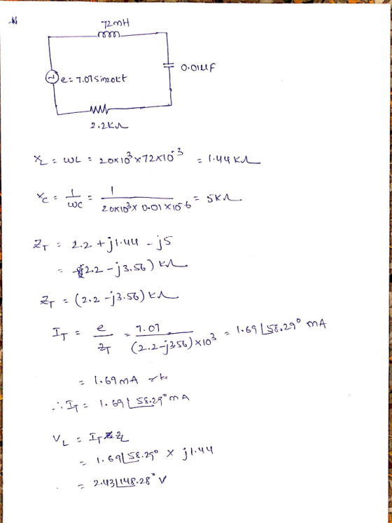
A. Using the rated component values, calculate XL, XC, ZT.
Draw the impedance phasor diagram.
B....
frequency=5000 a) Calculate values for XL,Xc and ZT. b) Calculate I (phasor format) for the circuit....
 frequency=5000
a) Calculate values for XL,Xc and ZT.
b) Calculate I (phasor format) for the circuit.
c) Calculate the voltage (phasor format) drop across the
resistor (VR1), the inductor (VL1 ) and capacitor (Vc1)
xsci L1 15mH 0.033 R1 Fcn Gen RS 50Ω V1 510Ω
frequency=5000
a) Calculate values for XL,Xc and ZT.
b) Calculate I (phasor format) for the circuit.
c) Calculate the voltage (phasor format) drop across the
resistor (VR1), the inductor (VL1 ) and capacitor (Vc1)
xsci L1 15mH 0.033 R1 Fcn Gen RS 50Ω V1 510Ω
ame Su chool Number 4: : The source voltage of the circuit below is V()-140cos(30). The component values are RI-20, XL-30. Xc-20 a) Determine the load impedance Zab that will absorb maximum power if...
 ame Su chool Number 4: : The source voltage of the circuit below is V()-140cos(30). The component values are RI-20, XL-30. Xc-20 a) Determine the load impedance Zab that will absorb maximum power if it is connected to terminals a-b of the circuit below. b) Determine the maximum power absorbed by this load. Xc XL. M-0.8H R1 2-2 0.4H Vit)
ame Su chool Number 4: : The source voltage of the circuit below is V()-140cos(30). The component values are RI-20,...
ame Su chool Number 4: : The source voltage of the circuit below is V()-140cos(30). The component values are RI-20, XL-30. Xc-20 a) Determine the load impedance Zab that will absorb maximum power if it is connected to terminals a-b of the circuit below. b) Determine the maximum power absorbed by this load. Xc XL. M-0.8H R1 2-2 0.4H Vit)
ame Su chool Number 4: : The source voltage of the circuit below is V()-140cos(30). The component values are RI-20,...
for the circuit below: a. Circuit Impedance in polar and rectangular form. b. Is the circuit...
 for the circuit below: a. Circuit Impedance in polar and rectangular form. b. Is the circuit more inductive or more capacitive? c. Draw the impedance phasor diagram. d. The net reactance that will make the impedance magnitude equal to 100 ohms. e. Itot, VR, VL, and VC in polar form. f. Draw the voltage phasor diagram. 47 2 80 2 35 22 4_ov frequency is 5KHz:
A resistance R = 10Ω, a capacitor C = 15μF, an inductor of L = 38mH,...
A resistance R = 10Ω, a capacitor C = 15μF, an inductor of L = 38mH, and an alternating current source with a voltage amplitude of 50V to 160Hz are connected in series. A- Calculate the angular frequency of the source B- Calculate the XL, XC, and Z impedance reactances C- Calculate the lag between the circuit current and the source voltage D- Calculate the amplitude of the circuit current and express the circuit current as a function of time...
Review Part A. Find the relationship between the phasor voltage and phasor current for a resistance...
 Review Part A. Find the relationship between the phasor voltage and phasor current for a resistance The resistor shown here has been transformed into the phasor domain: Ik 4k Suppose that the phasor current is given by IR = 752120 mA. Find the phasor voltage VR. Enter a complex number in polar form, with phase angle in degrees. View Available Hint(s) 3002120 V Submit Previous Answers Correct Part B - Draw the phasor diagram of the resistance from Part A...
9 (12 points) Consider the RLC circuit shown, powered by ε = Vo sin(at). (a) Draw...
 9 (12 points) Consider the RLC circuit shown, powered by ε = Vo sin(at). (a) Draw two phasor diagram, one for the current phasors 11, 12, and I (the total current), and the other for the voltage pahsors V, VI, Vc, and ε. (Hint: Note that I = 11 + 12, while VR = V2 + VC = ε. Draw the phasor diagrams accordingly.) (b) Find I as a function of time. (c) Find the impedance Z of the circuit....
2)Passive Filter: High Pass Filter Lab Experiment 3) Given the following RLC series circuit. V, =...
 2)Passive Filter: High Pass Filter Lab Experiment 3) Given the following RLC series circuit. V, = 10 Vrm L 0º and frequency f= 90 KHz. The circuit elements values are: R = 5 KO, L= 10 mH and C = 470 pF. a) Calculate total impedance Z, in polar form. b) Calculate total current I, in polar form. c) Calculate the voltages across R, C and L, (VR, Vc, and V.). d) Draw voltage phasor diagram Vs, VR, Vc, and...
1. Using circuit 3-1, calculate the total current (which is also the capacitor current and resistor...
 1. Using circuit 3-1, calculate the total current (which is also
the capacitor current and resistor current) by using Ohm’s Law. To
do this, you must first compute the total impedance of the circuit,
in polar form. Also, remember that Vs (source voltage) phase shift
is 0 degrees. Write your answer in polar form.
2. Compute the voltage across the capacitor (C1), using Ohm’s
Law and your result from #1. Write your answer in polar form.
3. In a series...
1. Using circuit 3-1, calculate the total current (which is also
the capacitor current and resistor current) by using Ohm’s Law. To
do this, you must first compute the total impedance of the circuit,
in polar form. Also, remember that Vs (source voltage) phase shift
is 0 degrees. Write your answer in polar form.
2. Compute the voltage across the capacitor (C1), using Ohm’s
Law and your result from #1. Write your answer in polar form.
3. In a series...
Can someone help me finish my prelab please? PROCEDURE (Pre-lab) Series: Draw a schematic diagram of...
Can someone help me finish my prelab please? PROCEDURE (Pre-lab) Series: Draw a schematic diagram of a series circuit consisting of a 24V d-c voltage source and 5 series resistors. Label the resistors R1 through R5. Use standard symbols to represent the voltage source and resistors. Also, make sure to label the REFERENCE (lowest point of potential). The resistor values to be used in the experiment are 220 Ω, 330 Ω, 470 Ω, 560 Ω, and 680 Ω. Label points...
I am currently trying to figure out the experiment below. Please complete Table 1 with an...
 I am currently trying to figure out the experiment below. Please
complete Table 1 with an explanation, I appreciate it thank
you! Promise to give thumbs up!
Introduction The phase differences between the output voltage, the voltage across the inductor, the voltage across the capacitor, and the voltage across the resistor will be examined at resonant frequency. The voltage and phase relationship will also be examined for frequencies above and below resonance. Theory An inductor, a capacitor, and a resistor are...
I am currently trying to figure out the experiment below. Please
complete Table 1 with an explanation, I appreciate it thank
you! Promise to give thumbs up!
Introduction The phase differences between the output voltage, the voltage across the inductor, the voltage across the capacitor, and the voltage across the resistor will be examined at resonant frequency. The voltage and phase relationship will also be examined for frequencies above and below resonance. Theory An inductor, a capacitor, and a resistor are...
 frequency=5000
a) Calculate values for XL,Xc and ZT.
b) Calculate I (phasor format) for the circuit.
c) Calculate the voltage (phasor format) drop across the
resistor (VR1), the inductor (VL1 ) and capacitor (Vc1)
xsci L1 15mH 0.033 R1 Fcn Gen RS 50Ω V1 510Ω
frequency=5000
a) Calculate values for XL,Xc and ZT.
b) Calculate I (phasor format) for the circuit.
c) Calculate the voltage (phasor format) drop across the
resistor (VR1), the inductor (VL1 ) and capacitor (Vc1)
xsci L1 15mH 0.033 R1 Fcn Gen RS 50Ω V1 510Ω
 ame Su chool Number 4: : The source voltage of the circuit below is V()-140cos(30). The component values are RI-20, XL-30. Xc-20 a) Determine the load impedance Zab that will absorb maximum power if it is connected to terminals a-b of the circuit below. b) Determine the maximum power absorbed by this load. Xc XL. M-0.8H R1 2-2 0.4H Vit)
ame Su chool Number 4: : The source voltage of the circuit below is V()-140cos(30). The component values are RI-20,...
ame Su chool Number 4: : The source voltage of the circuit below is V()-140cos(30). The component values are RI-20, XL-30. Xc-20 a) Determine the load impedance Zab that will absorb maximum power if it is connected to terminals a-b of the circuit below. b) Determine the maximum power absorbed by this load. Xc XL. M-0.8H R1 2-2 0.4H Vit)
ame Su chool Number 4: : The source voltage of the circuit below is V()-140cos(30). The component values are RI-20,...
 for the circuit below: a. Circuit Impedance in polar and rectangular form. b. Is the circuit more inductive or more capacitive? c. Draw the impedance phasor diagram. d. The net reactance that will make the impedance magnitude equal to 100 ohms. e. Itot, VR, VL, and VC in polar form. f. Draw the voltage phasor diagram. 47 2 80 2 35 22 4_ov frequency is 5KHz:
 Review Part A. Find the relationship between the phasor voltage and phasor current for a resistance The resistor shown here has been transformed into the phasor domain: Ik 4k Suppose that the phasor current is given by IR = 752120 mA. Find the phasor voltage VR. Enter a complex number in polar form, with phase angle in degrees. View Available Hint(s) 3002120 V Submit Previous Answers Correct Part B - Draw the phasor diagram of the resistance from Part A...
 9 (12 points) Consider the RLC circuit shown, powered by ε = Vo sin(at). (a) Draw two phasor diagram, one for the current phasors 11, 12, and I (the total current), and the other for the voltage pahsors V, VI, Vc, and ε. (Hint: Note that I = 11 + 12, while VR = V2 + VC = ε. Draw the phasor diagrams accordingly.) (b) Find I as a function of time. (c) Find the impedance Z of the circuit....
 2)Passive Filter: High Pass Filter Lab Experiment 3) Given the following RLC series circuit. V, = 10 Vrm L 0º and frequency f= 90 KHz. The circuit elements values are: R = 5 KO, L= 10 mH and C = 470 pF. a) Calculate total impedance Z, in polar form. b) Calculate total current I, in polar form. c) Calculate the voltages across R, C and L, (VR, Vc, and V.). d) Draw voltage phasor diagram Vs, VR, Vc, and...
 1. Using circuit 3-1, calculate the total current (which is also
the capacitor current and resistor current) by using Ohm’s Law. To
do this, you must first compute the total impedance of the circuit,
in polar form. Also, remember that Vs (source voltage) phase shift
is 0 degrees. Write your answer in polar form.
2. Compute the voltage across the capacitor (C1), using Ohm’s
Law and your result from #1. Write your answer in polar form.
3. In a series...
1. Using circuit 3-1, calculate the total current (which is also
the capacitor current and resistor current) by using Ohm’s Law. To
do this, you must first compute the total impedance of the circuit,
in polar form. Also, remember that Vs (source voltage) phase shift
is 0 degrees. Write your answer in polar form.
2. Compute the voltage across the capacitor (C1), using Ohm’s
Law and your result from #1. Write your answer in polar form.
3. In a series...
 I am currently trying to figure out the experiment below. Please
complete Table 1 with an explanation, I appreciate it thank
you! Promise to give thumbs up!
Introduction The phase differences between the output voltage, the voltage across the inductor, the voltage across the capacitor, and the voltage across the resistor will be examined at resonant frequency. The voltage and phase relationship will also be examined for frequencies above and below resonance. Theory An inductor, a capacitor, and a resistor are...
I am currently trying to figure out the experiment below. Please
complete Table 1 with an explanation, I appreciate it thank
you! Promise to give thumbs up!
Introduction The phase differences between the output voltage, the voltage across the inductor, the voltage across the capacitor, and the voltage across the resistor will be examined at resonant frequency. The voltage and phase relationship will also be examined for frequencies above and below resonance. Theory An inductor, a capacitor, and a resistor are...
Most questions answered within 3 hours.
-
Where is the error in this code sequence?
String s1 = "Hello";
String s2 = "ello";...
asked 10 months ago -
Financial data for Joel de Paris, Inc., for last year
follow:
Joel de Paris, Inc.
Balance...
asked 10 months ago -
Consider this reaction:
Al2(SO4)3 (aq)+ BaCl3
(aq) Al2Cl6 (aq)- +
3BaSO4(s) . What is the...
asked 10 months ago -
Suppose that Savneet is considering increasing her
recent random sample from 20 car rentals to 40...
asked 10 months ago -
Trucks arrive at an unloading terminal at an average rate of 120
per hour.
Trucks arrive...
asked 10 months ago -
Why are methanol and ethanol completely soluble in water while
octanol is not very little soluble....
asked 10 months ago -
A facilities manager at a university reads in a research report
that the mean amount of...
asked 10 months ago -
When the CuSO4 is rehydrated by adding water to the anhydrous
compound, is this an endothermic...
asked 10 months ago -
A ray of sunlight is passing from diamond into crown glass; the
angle of incidence is...
asked 10 months ago -
A block of mass 0.249 kg is placed on top of a light, vertical
spring of...
asked 10 months ago -
how do the kidneys compensate in the presences of acidosis
a) trigger hyperventilate
b) reserve acid...
asked 10 months ago -
Question 501 pts
The rental rate of capital to the firm increases. Which of the
following...
asked 10 months ago