
Homework Answers


Add Answer to:
ANALYTICAL ANALYTICAL- ANALYTICAL- ANALYTICAL-ANALYTICAL 4 Bar Position Analysis ANALYTICAL-ANALYTICAL-ANALYTICAL Given: The following 4 bar mechanism. Find:...
Please Solve and Give Detail. Thank you. For a four-bar mechanism, the link lengths in inches...
 Please Solve and Give Detail. Thank you.
For a four-bar mechanism, the link lengths in inches and the value of the angle 02 are as follows: Link 1-5, Link 2-3, Link 3-8, Link 4-9, θ. = 45 degrees. Link l is the ground and link 2 is the driving link. (a) Is this a crank-rocker, double rocker, double crank or triple rocker mechanism? Justify your answer. [5 points] (b) Find the angles 0.04 and transmission angle when θ2 45 degrees...
Please Solve and Give Detail. Thank you.
For a four-bar mechanism, the link lengths in inches and the value of the angle 02 are as follows: Link 1-5, Link 2-3, Link 3-8, Link 4-9, θ. = 45 degrees. Link l is the ground and link 2 is the driving link. (a) Is this a crank-rocker, double rocker, double crank or triple rocker mechanism? Justify your answer. [5 points] (b) Find the angles 0.04 and transmission angle when θ2 45 degrees...
(20 pts) Problem 4. Consider the four bar mechanism below. kD4B-40°, BC-2.5it lj , CD-3.3 and AD- 6i. Find the possible lengths of Link 1 and the corresponding valtues of o We were unable to transcri...
 (20 pts) Problem 4. Consider the four bar mechanism below. kD4B-40°, BC-2.5it lj , CD-3.3 and AD- 6i. Find the possible lengths of Link 1 and the corresponding valtues of o We were unable to transcribe this image
(20 pts) Problem 4. Consider the four bar mechanism below. kD4B-40°, BC-2.5it lj , CD-3.3 and AD- 6i. Find the possible lengths of Link 1 and the corresponding valtues of o
(20 pts) Problem 4. Consider the four bar mechanism below. kD4B-40°, BC-2.5it lj , CD-3.3 and AD- 6i. Find the possible lengths of Link 1 and the corresponding valtues of o We were unable to transcribe this image
(20 pts) Problem 4. Consider the four bar mechanism below. kD4B-40°, BC-2.5it lj , CD-3.3 and AD- 6i. Find the possible lengths of Link 1 and the corresponding valtues of o
kinematic Problem #4 [CLO 3] [25 Pts). Using Complex Numbers Method, In the mechanism shown, AB...
 kinematic
Problem #4 [CLO 3] [25 Pts). Using Complex Numbers Method, In the mechanism shown, AB = 8 cm, CB BD 4 em. If link 4 is translating rightward with constant velocity of 5 m/sec. At an instant when 0= 45, determine: a) Distance AC and the angular position of link 2 b) The angular velocities of links 2 and 3. w c) Velocity of point D. D 3 A 03
Problem #4 [CLO 3] [25 Pts). Using Complex Numbers...
kinematic
Problem #4 [CLO 3] [25 Pts). Using Complex Numbers Method, In the mechanism shown, AB = 8 cm, CB BD 4 em. If link 4 is translating rightward with constant velocity of 5 m/sec. At an instant when 0= 45, determine: a) Distance AC and the angular position of link 2 b) The angular velocities of links 2 and 3. w c) Velocity of point D. D 3 A 03
Problem #4 [CLO 3] [25 Pts). Using Complex Numbers...
3. Question 1. According to the question Exam duration is 120 minutes and questlons u Return mechanism is shown with di...
 3. Question 1. According to the question
Exam duration is 120 minutes and questlons u Return mechanism is shown with dimensions. At the given instant crank AB is on. For a graphical position analysis, draw the mechanism to scale and B and C, and angle θ4 . Then, write down the loop equation of he vector loop shown below and separate the loop equation into en by solving the component equations, calculate L and 04. Do the results 1) In...
3. Question 1. According to the question
Exam duration is 120 minutes and questlons u Return mechanism is shown with dimensions. At the given instant crank AB is on. For a graphical position analysis, draw the mechanism to scale and B and C, and angle θ4 . Then, write down the loop equation of he vector loop shown below and separate the loop equation into en by solving the component equations, calculate L and 04. Do the results 1) In...
(20%) posmoN ANALYSIS, A mechanism consists of 4 links: Link 1: ground, R 120 in, endpoints A & D, shown below. Link 2: moving, endpoints A & B, R = 40 in, θ,-65° Link 3: moving, endpoint...
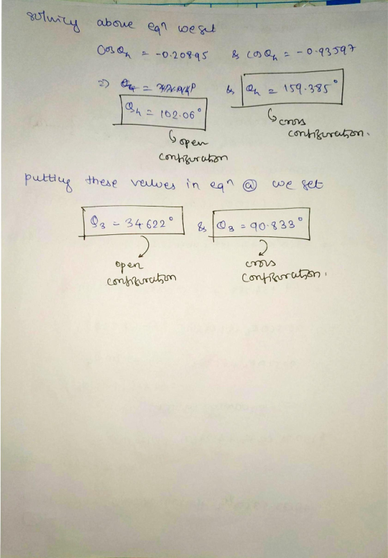
 (20%) posmoN ANALYSIS, A mechanism consists of 4 links: Link 1: ground, R 120 in, endpoints A & D, shown below. Link 2: moving, endpoints A & B, R = 40 in, θ,-65° Link 3: moving, endpoints B & C, R 45 in Link 4: moving, endpoints C & D, R = 145 in Unknowns: 03 (angle of Link 3) & 04 (angle of Link 4) There are two possible solutions for the position of this mechanism. Find both unknowns...
Problem # 4 ( CLO 3) (25 Pts). Using Complex Numbers Methed. In the mechanism shown,...
 Problem # 4 ( CLO 3) (25 Pts). Using Complex Numbers Methed. In the mechanism shown, AB-8 em. CB BD-4 cm 1 fik 4 is traanslating riahtward with constant velocity of 5 m/sec.. At an instant when 6,-45, determine: Distance AC and the angular position of link 2 b) The angular velocities of links 2 and 3. Velocity of point D. c) B 03
Problem # 4 ( CLO 3) (25 Pts). Using Complex Numbers Methed. In the mechanism shown,...
Problem # 4 ( CLO 3) (25 Pts). Using Complex Numbers Methed. In the mechanism shown, AB-8 em. CB BD-4 cm 1 fik 4 is traanslating riahtward with constant velocity of 5 m/sec.. At an instant when 6,-45, determine: Distance AC and the angular position of link 2 b) The angular velocities of links 2 and 3. Velocity of point D. c) B 03
Problem # 4 ( CLO 3) (25 Pts). Using Complex Numbers Methed. In the mechanism shown,...
Problem # 4 ( CLO 3) (25 Pts). Using Complex Numbers Methed. In the mechanism shown,...
 Problem # 4 ( CLO 3) (25 Pts). Using Complex Numbers Methed. In the mechanism shown, AB-8 em. CB BD-4 cm 1 fik 4 is traanslating riahtward with constant velocity of 5 m/sec.. At an instant when 6,-45, determine: Distance AC and the angular position of link 2 b) The angular velocities of links 2 and 3. Velocity of point D. c) B 03
Problem # 4 ( CLO 3) (25 Pts). Using Complex Numbers Methed. In the mechanism shown,...
Problem # 4 ( CLO 3) (25 Pts). Using Complex Numbers Methed. In the mechanism shown, AB-8 em. CB BD-4 cm 1 fik 4 is traanslating riahtward with constant velocity of 5 m/sec.. At an instant when 6,-45, determine: Distance AC and the angular position of link 2 b) The angular velocities of links 2 and 3. Velocity of point D. c) B 03
Problem # 4 ( CLO 3) (25 Pts). Using Complex Numbers Methed. In the mechanism shown,...
ine given 4) In the figure aside, an in-line slider- crank mechanism is shown. a) Calculate the velocity of the cou...
 ine given 4) In the figure aside, an in-line slider- crank mechanism is shown. a) Calculate the velocity of the coupler point D if crank AB is rotating CW wilth a speed of 2 rad/sec b) Calculate the necessary crank if the velocity of the coupler point is required to be 50 cm/sec, at the given position. speed AB 5am BC-10cm 0 30 degrees
ine given 4) In the figure aside, an in-line slider- crank mechanism is shown. a) Calculate...
ine given 4) In the figure aside, an in-line slider- crank mechanism is shown. a) Calculate the velocity of the coupler point D if crank AB is rotating CW wilth a speed of 2 rad/sec b) Calculate the necessary crank if the velocity of the coupler point is required to be 50 cm/sec, at the given position. speed AB 5am BC-10cm 0 30 degrees
ine given 4) In the figure aside, an in-line slider- crank mechanism is shown. a) Calculate...
P4.2: The four-bar mechanism in Figure P4.2 has the link lengths: LAB = 4", LED =...
 P4.2: The four-bar mechanism in Figure P4.2 has the link lengths: LAB = 4", LED = 24", Loc = 14", LA = 30". The location of COM is as follows: LAG = 2.120"; LEG2 = 11.863"; LDG = 6.722". The crank 1 rotates counterclockwise with the angular displacement 8. = 27t-t [rad), angular velocity 0. = , = 21 [rad/s], and angular accelera- tion &= 7= 0 [rad/s). The mass and moment of inertia relative to each link's COM are...
Design a 4-bar linkage that can put the coupler link AB in the three positions shown...
 Design a 4-bar linkage that can put the coupler link AB in the three positions shown in the figure below. The length of AB is 1.25 cm. The numbers beside A1, A2 and A3 are the coordinates of pin A in the three precision positions. You will probably find it helpful to scale the drawing to a more convenient size to work on. Submit your drawing of the designed mechanism (showing it drawn clearly in all three positions as well...
 Please Solve and Give Detail. Thank you.
For a four-bar mechanism, the link lengths in inches and the value of the angle 02 are as follows: Link 1-5, Link 2-3, Link 3-8, Link 4-9, θ. = 45 degrees. Link l is the ground and link 2 is the driving link. (a) Is this a crank-rocker, double rocker, double crank or triple rocker mechanism? Justify your answer. [5 points] (b) Find the angles 0.04 and transmission angle when θ2 45 degrees...
Please Solve and Give Detail. Thank you.
For a four-bar mechanism, the link lengths in inches and the value of the angle 02 are as follows: Link 1-5, Link 2-3, Link 3-8, Link 4-9, θ. = 45 degrees. Link l is the ground and link 2 is the driving link. (a) Is this a crank-rocker, double rocker, double crank or triple rocker mechanism? Justify your answer. [5 points] (b) Find the angles 0.04 and transmission angle when θ2 45 degrees...
 (20 pts) Problem 4. Consider the four bar mechanism below. kD4B-40°, BC-2.5it lj , CD-3.3 and AD- 6i. Find the possible lengths of Link 1 and the corresponding valtues of o We were unable to transcribe this image
(20 pts) Problem 4. Consider the four bar mechanism below. kD4B-40°, BC-2.5it lj , CD-3.3 and AD- 6i. Find the possible lengths of Link 1 and the corresponding valtues of o
(20 pts) Problem 4. Consider the four bar mechanism below. kD4B-40°, BC-2.5it lj , CD-3.3 and AD- 6i. Find the possible lengths of Link 1 and the corresponding valtues of o We were unable to transcribe this image
(20 pts) Problem 4. Consider the four bar mechanism below. kD4B-40°, BC-2.5it lj , CD-3.3 and AD- 6i. Find the possible lengths of Link 1 and the corresponding valtues of o
 kinematic
Problem #4 [CLO 3] [25 Pts). Using Complex Numbers Method, In the mechanism shown, AB = 8 cm, CB BD 4 em. If link 4 is translating rightward with constant velocity of 5 m/sec. At an instant when 0= 45, determine: a) Distance AC and the angular position of link 2 b) The angular velocities of links 2 and 3. w c) Velocity of point D. D 3 A 03
Problem #4 [CLO 3] [25 Pts). Using Complex Numbers...
kinematic
Problem #4 [CLO 3] [25 Pts). Using Complex Numbers Method, In the mechanism shown, AB = 8 cm, CB BD 4 em. If link 4 is translating rightward with constant velocity of 5 m/sec. At an instant when 0= 45, determine: a) Distance AC and the angular position of link 2 b) The angular velocities of links 2 and 3. w c) Velocity of point D. D 3 A 03
Problem #4 [CLO 3] [25 Pts). Using Complex Numbers...
 3. Question 1. According to the question
Exam duration is 120 minutes and questlons u Return mechanism is shown with dimensions. At the given instant crank AB is on. For a graphical position analysis, draw the mechanism to scale and B and C, and angle θ4 . Then, write down the loop equation of he vector loop shown below and separate the loop equation into en by solving the component equations, calculate L and 04. Do the results 1) In...
3. Question 1. According to the question
Exam duration is 120 minutes and questlons u Return mechanism is shown with dimensions. At the given instant crank AB is on. For a graphical position analysis, draw the mechanism to scale and B and C, and angle θ4 . Then, write down the loop equation of he vector loop shown below and separate the loop equation into en by solving the component equations, calculate L and 04. Do the results 1) In...
 (20%) posmoN ANALYSIS, A mechanism consists of 4 links: Link 1: ground, R 120 in, endpoints A & D, shown below. Link 2: moving, endpoints A & B, R = 40 in, θ,-65° Link 3: moving, endpoints B & C, R 45 in Link 4: moving, endpoints C & D, R = 145 in Unknowns: 03 (angle of Link 3) & 04 (angle of Link 4) There are two possible solutions for the position of this mechanism. Find both unknowns...
 Problem # 4 ( CLO 3) (25 Pts). Using Complex Numbers Methed. In the mechanism shown, AB-8 em. CB BD-4 cm 1 fik 4 is traanslating riahtward with constant velocity of 5 m/sec.. At an instant when 6,-45, determine: Distance AC and the angular position of link 2 b) The angular velocities of links 2 and 3. Velocity of point D. c) B 03
Problem # 4 ( CLO 3) (25 Pts). Using Complex Numbers Methed. In the mechanism shown,...
Problem # 4 ( CLO 3) (25 Pts). Using Complex Numbers Methed. In the mechanism shown, AB-8 em. CB BD-4 cm 1 fik 4 is traanslating riahtward with constant velocity of 5 m/sec.. At an instant when 6,-45, determine: Distance AC and the angular position of link 2 b) The angular velocities of links 2 and 3. Velocity of point D. c) B 03
Problem # 4 ( CLO 3) (25 Pts). Using Complex Numbers Methed. In the mechanism shown,...
 ine given 4) In the figure aside, an in-line slider- crank mechanism is shown. a) Calculate the velocity of the coupler point D if crank AB is rotating CW wilth a speed of 2 rad/sec b) Calculate the necessary crank if the velocity of the coupler point is required to be 50 cm/sec, at the given position. speed AB 5am BC-10cm 0 30 degrees
ine given 4) In the figure aside, an in-line slider- crank mechanism is shown. a) Calculate...
ine given 4) In the figure aside, an in-line slider- crank mechanism is shown. a) Calculate the velocity of the coupler point D if crank AB is rotating CW wilth a speed of 2 rad/sec b) Calculate the necessary crank if the velocity of the coupler point is required to be 50 cm/sec, at the given position. speed AB 5am BC-10cm 0 30 degrees
ine given 4) In the figure aside, an in-line slider- crank mechanism is shown. a) Calculate...
 P4.2: The four-bar mechanism in Figure P4.2 has the link lengths: LAB = 4", LED = 24", Loc = 14", LA = 30". The location of COM is as follows: LAG = 2.120"; LEG2 = 11.863"; LDG = 6.722". The crank 1 rotates counterclockwise with the angular displacement 8. = 27t-t [rad), angular velocity 0. = , = 21 [rad/s], and angular accelera- tion &= 7= 0 [rad/s). The mass and moment of inertia relative to each link's COM are...
 Design a 4-bar linkage that can put the coupler link AB in the three positions shown in the figure below. The length of AB is 1.25 cm. The numbers beside A1, A2 and A3 are the coordinates of pin A in the three precision positions. You will probably find it helpful to scale the drawing to a more convenient size to work on. Submit your drawing of the designed mechanism (showing it drawn clearly in all three positions as well...
Most questions answered within 3 hours.
-
Where is the error in this code sequence?
String s1 = "Hello";
String s2 = "ello";...
asked 10 months ago -
Financial data for Joel de Paris, Inc., for last year
follow:
Joel de Paris, Inc.
Balance...
asked 10 months ago -
Consider this reaction:
Al2(SO4)3 (aq)+ BaCl3
(aq) Al2Cl6 (aq)- +
3BaSO4(s) . What is the...
asked 10 months ago -
Suppose that Savneet is considering increasing her
recent random sample from 20 car rentals to 40...
asked 10 months ago -
Trucks arrive at an unloading terminal at an average rate of 120
per hour.
Trucks arrive...
asked 10 months ago -
Why are methanol and ethanol completely soluble in water while
octanol is not very little soluble....
asked 10 months ago -
A facilities manager at a university reads in a research report
that the mean amount of...
asked 10 months ago -
When the CuSO4 is rehydrated by adding water to the anhydrous
compound, is this an endothermic...
asked 10 months ago -
A ray of sunlight is passing from diamond into crown glass; the
angle of incidence is...
asked 10 months ago -
A block of mass 0.249 kg is placed on top of a light, vertical
spring of...
asked 10 months ago -
how do the kidneys compensate in the presences of acidosis
a) trigger hyperventilate
b) reserve acid...
asked 10 months ago -
Question 501 pts
The rental rate of capital to the firm increases. Which of the
following...
asked 10 months ago