Construct a clamper circuit with the following requirements: C = 20 uF R = 300 Vin...
-
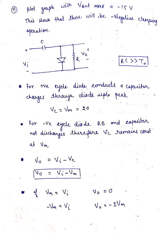
Construct a clamper circuit with the following requirements:
-
C = 20 uF
-
R = 300
-
Vin = 20 Vpk AC, F = 1 KHz
-
Obtain 2 graphs
-
One with Vout min = 1 V
-
One with Vout max = -15 V
-
-
You must show Vin and Vout on the graphs.
-
Homework Answers


Add Answer to:
Construct a clamper circuit with the following requirements:
C = 20 uF
R = 300
Vin...
IV, Laboratory Procedure 1. Construct the circuit of Figure 6.1, measure the current value 2. Con...
 IV, Laboratory Procedure 1. Construct the circuit of Figure 6.1, measure the current value 2. Construct the circuit of Figure 6.2; measure Vn and v., using the oscilloscope. 3. Construct the circuit of Figure 6.3, measure the value of Io and V 4. Construct the clipper design circuit, Capture the input and output waveforms. 5. Construct your clamper design circuit. Capture the input and output waveforms Figure 6.3 Design a clipper circuit which limits input signals to +3V and -2V....
6) Buck converter has: Vin =20 V, L=10 mH, C=20 uF, R=20 ohm, switching frequency f=20...
6) Buck converter has: Vin =20 V, L=10 mH, C=20 uF, R=20 ohm, switching frequency f=20 kHz and switching duty cycle D=0.6. Calculate the average output voltage and current ripple?
Problem 5: (20 points) Given the following circuit VIN L Vout R a) Write the loop...
 Problem 5: (20 points) Given the following circuit VIN L Vout R a) Write the loop equation for the circuit, and then find the transfer function Vout(s) H(S) = Express H(s) so that the coefficient of the s in the denominator is 1. Vin(s) b) If Vin(t) is 20u(t), find out(t). c) If Vin(t) is 20u(t) find the final value using the final value theorem (show your work), d) Assume (R/L) = 10, if the input is Vin(t) = 100...
A series L-R-C circuit is driven with AC voltage of amplitude Vin and frequency ω. Define...
 A series L-R-C circuit is driven with AC voltage of
amplitude Vin and frequency ω. Define Vout to be the amplitude of
the voltage across the capacitor. The resistance of the resistor is
R, the capacitance of the capacitor is C, and the inductance of the
inductor is L.(Figure 1)
What is the ratio VoutVin?
Express your answer in terms of either R, ω, L, and C or R, XL
=ωL, and XC =1ωC.
Vin c+ Vout
A series L-R-C circuit is driven with AC voltage of
amplitude Vin and frequency ω. Define Vout to be the amplitude of
the voltage across the capacitor. The resistance of the resistor is
R, the capacitance of the capacitor is C, and the inductance of the
inductor is L.(Figure 1)
What is the ratio VoutVin?
Express your answer in terms of either R, ω, L, and C or R, XL
=ωL, and XC =1ωC.
Vin c+ Vout
1k luF 10nF VIN(t) C r(t) oUr Figure 1. Bandpass circuit Only for this assignment, you will do a ...
 1k luF 10nF VIN(t) C r(t) oUr Figure 1. Bandpass circuit Only for this assignment, you will do a small Multisim assignment. Remember, you still need to know Multisim operation even if you are in the hardware in homework group You will build the circuit shown in Fig. 1 in Multisim and then need to use AC analysis option to generate the bode plot. Choose frequencies in between 10 Hz and 100 kHz and select linear scale on magnitude plot....
3-F) b. Vout = 0.99 Vin 3-E) For the following circuit, with Ri 18 k2, R2...
 3-F) b. Vout = 0.99 Vin
3-E) For the following circuit, with Ri 18 k2, R2 15 k(2, R6 = 40 kQ, V,-10 V, and V,-7 V, find: 22 k2, R 30 k2, R4 20 kQ, Rs- a) the current through Ri, R3, & R6 b) the voltage across R2, R4, & Rs Rs V, 3-F) For the following circuit, what is Vout in terms of Vin for each case? a) R1-100 ?, R2-1 k(2, and R3 = 1.0 M(2...
3-F) b. Vout = 0.99 Vin
3-E) For the following circuit, with Ri 18 k2, R2 15 k(2, R6 = 40 kQ, V,-10 V, and V,-7 V, find: 22 k2, R 30 k2, R4 20 kQ, Rs- a) the current through Ri, R3, & R6 b) the voltage across R2, R4, & Rs Rs V, 3-F) For the following circuit, what is Vout in terms of Vin for each case? a) R1-100 ?, R2-1 k(2, and R3 = 1.0 M(2...
Question 1 : [20 points) For the circuit below: R C = + + Vin L...
 Question 1 : [20 points) For the circuit below: R C = + + Vin L Vout O Given that: R= 241, ZŁ= 88 N and Zc = N. Answer the following a. Calculate the input Admittance Yin(s) =1/ Zin(s b. Consider Yin(s) as the system's transfer function, calculate the following: (6 points) (10 points) OZOZ ISSOTO 1. Wp: 2. Bw: 3. W1 and 22: 4. Hm: C. Draw the second order respo on the graph below (show W1,W2, HM...
Review | Constants A series L-R-C circuit is driven with AC voltage of amplitude Vin and...
 Review | Constants A series L-R-C circuit is driven with AC voltage of amplitude Vin and frequency w. Define Vout to be the amplitude of the voltage across the capacitor. The resistance of the resistor is R, the capacitance of the capacitor is C, and the inductance of the inductor is L. (Figure 1) Part A What is the ratio Viin Figure Express your answer in terms of either R, w, L, and C or R, XL = wl, and...
Problem 1. (40 pts): A student in ME 345 shows you the following circuit with R=1.0...
 Problem 1. (40 pts): A student in ME 345 shows you the following circuit with R=1.0 k 2 and C = 1.0 uF Vout Vin c= a. What kind of circuit is this? What is the order of this dynamic system? b. Using KVL/KCL, derive the differential equation and put in standard form. What is the static sensitivity K of this system? c. What is the cutoff frequency (@c) of this circuit? What is the time constant (c)? How are...
I need help with numbers 4,6,7,8,9 please? 12 VDC 1.0 k ohms 10k ohms C3 1.0 uF C1 1.0 UF , R Load Baca 1 80 10k ohns 300 mVp-p 1.0 kHz 100 ohms .7k ohms C2 47uF 330 ohms 4. Calculate the following pa...
 I need help with numbers 4,6,7,8,9 please?
12 VDC 1.0 k ohms 10k ohms C3 1.0 uF C1 1.0 UF , R Load Baca 1 80 10k ohns 300 mVp-p 1.0 kHz 100 ohms .7k ohms C2 47uF 330 ohms 4. Calculate the following parameters assuming capacitor C2 has been removed from the circuit with the 1.0k2 resistor as the load. RIN BASE Av Vour 5. Construct the circuit shown on the previous page. Before connecting the AC supply, measure...
I need help with numbers 4,6,7,8,9 please?
12 VDC 1.0 k ohms 10k ohms C3 1.0 uF C1 1.0 UF , R Load Baca 1 80 10k ohns 300 mVp-p 1.0 kHz 100 ohms .7k ohms C2 47uF 330 ohms 4. Calculate the following parameters assuming capacitor C2 has been removed from the circuit with the 1.0k2 resistor as the load. RIN BASE Av Vour 5. Construct the circuit shown on the previous page. Before connecting the AC supply, measure...
 IV, Laboratory Procedure 1. Construct the circuit of Figure 6.1, measure the current value 2. Construct the circuit of Figure 6.2; measure Vn and v., using the oscilloscope. 3. Construct the circuit of Figure 6.3, measure the value of Io and V 4. Construct the clipper design circuit, Capture the input and output waveforms. 5. Construct your clamper design circuit. Capture the input and output waveforms Figure 6.3 Design a clipper circuit which limits input signals to +3V and -2V....
 Problem 5: (20 points) Given the following circuit VIN L Vout R a) Write the loop equation for the circuit, and then find the transfer function Vout(s) H(S) = Express H(s) so that the coefficient of the s in the denominator is 1. Vin(s) b) If Vin(t) is 20u(t), find out(t). c) If Vin(t) is 20u(t) find the final value using the final value theorem (show your work), d) Assume (R/L) = 10, if the input is Vin(t) = 100...
 A series L-R-C circuit is driven with AC voltage of
amplitude Vin and frequency ω. Define Vout to be the amplitude of
the voltage across the capacitor. The resistance of the resistor is
R, the capacitance of the capacitor is C, and the inductance of the
inductor is L.(Figure 1)
What is the ratio VoutVin?
Express your answer in terms of either R, ω, L, and C or R, XL
=ωL, and XC =1ωC.
Vin c+ Vout
A series L-R-C circuit is driven with AC voltage of
amplitude Vin and frequency ω. Define Vout to be the amplitude of
the voltage across the capacitor. The resistance of the resistor is
R, the capacitance of the capacitor is C, and the inductance of the
inductor is L.(Figure 1)
What is the ratio VoutVin?
Express your answer in terms of either R, ω, L, and C or R, XL
=ωL, and XC =1ωC.
Vin c+ Vout
 1k luF 10nF VIN(t) C r(t) oUr Figure 1. Bandpass circuit Only for this assignment, you will do a small Multisim assignment. Remember, you still need to know Multisim operation even if you are in the hardware in homework group You will build the circuit shown in Fig. 1 in Multisim and then need to use AC analysis option to generate the bode plot. Choose frequencies in between 10 Hz and 100 kHz and select linear scale on magnitude plot....
 3-F) b. Vout = 0.99 Vin
3-E) For the following circuit, with Ri 18 k2, R2 15 k(2, R6 = 40 kQ, V,-10 V, and V,-7 V, find: 22 k2, R 30 k2, R4 20 kQ, Rs- a) the current through Ri, R3, & R6 b) the voltage across R2, R4, & Rs Rs V, 3-F) For the following circuit, what is Vout in terms of Vin for each case? a) R1-100 ?, R2-1 k(2, and R3 = 1.0 M(2...
3-F) b. Vout = 0.99 Vin
3-E) For the following circuit, with Ri 18 k2, R2 15 k(2, R6 = 40 kQ, V,-10 V, and V,-7 V, find: 22 k2, R 30 k2, R4 20 kQ, Rs- a) the current through Ri, R3, & R6 b) the voltage across R2, R4, & Rs Rs V, 3-F) For the following circuit, what is Vout in terms of Vin for each case? a) R1-100 ?, R2-1 k(2, and R3 = 1.0 M(2...
 Question 1 : [20 points) For the circuit below: R C = + + Vin L Vout O Given that: R= 241, ZŁ= 88 N and Zc = N. Answer the following a. Calculate the input Admittance Yin(s) =1/ Zin(s b. Consider Yin(s) as the system's transfer function, calculate the following: (6 points) (10 points) OZOZ ISSOTO 1. Wp: 2. Bw: 3. W1 and 22: 4. Hm: C. Draw the second order respo on the graph below (show W1,W2, HM...
 Review | Constants A series L-R-C circuit is driven with AC voltage of amplitude Vin and frequency w. Define Vout to be the amplitude of the voltage across the capacitor. The resistance of the resistor is R, the capacitance of the capacitor is C, and the inductance of the inductor is L. (Figure 1) Part A What is the ratio Viin Figure Express your answer in terms of either R, w, L, and C or R, XL = wl, and...
 Problem 1. (40 pts): A student in ME 345 shows you the following circuit with R=1.0 k 2 and C = 1.0 uF Vout Vin c= a. What kind of circuit is this? What is the order of this dynamic system? b. Using KVL/KCL, derive the differential equation and put in standard form. What is the static sensitivity K of this system? c. What is the cutoff frequency (@c) of this circuit? What is the time constant (c)? How are...
 I need help with numbers 4,6,7,8,9 please?
12 VDC 1.0 k ohms 10k ohms C3 1.0 uF C1 1.0 UF , R Load Baca 1 80 10k ohns 300 mVp-p 1.0 kHz 100 ohms .7k ohms C2 47uF 330 ohms 4. Calculate the following parameters assuming capacitor C2 has been removed from the circuit with the 1.0k2 resistor as the load. RIN BASE Av Vour 5. Construct the circuit shown on the previous page. Before connecting the AC supply, measure...
I need help with numbers 4,6,7,8,9 please?
12 VDC 1.0 k ohms 10k ohms C3 1.0 uF C1 1.0 UF , R Load Baca 1 80 10k ohns 300 mVp-p 1.0 kHz 100 ohms .7k ohms C2 47uF 330 ohms 4. Calculate the following parameters assuming capacitor C2 has been removed from the circuit with the 1.0k2 resistor as the load. RIN BASE Av Vour 5. Construct the circuit shown on the previous page. Before connecting the AC supply, measure...
Most questions answered within 3 hours.
-
Where is the error in this code sequence?
String s1 = "Hello";
String s2 = "ello";...
asked 10 months ago -
Financial data for Joel de Paris, Inc., for last year
follow:
Joel de Paris, Inc.
Balance...
asked 10 months ago -
Consider this reaction:
Al2(SO4)3 (aq)+ BaCl3
(aq) Al2Cl6 (aq)- +
3BaSO4(s) . What is the...
asked 10 months ago -
Suppose that Savneet is considering increasing her
recent random sample from 20 car rentals to 40...
asked 10 months ago -
Trucks arrive at an unloading terminal at an average rate of 120
per hour.
Trucks arrive...
asked 10 months ago -
Why are methanol and ethanol completely soluble in water while
octanol is not very little soluble....
asked 10 months ago -
A facilities manager at a university reads in a research report
that the mean amount of...
asked 10 months ago -
When the CuSO4 is rehydrated by adding water to the anhydrous
compound, is this an endothermic...
asked 10 months ago -
A ray of sunlight is passing from diamond into crown glass; the
angle of incidence is...
asked 10 months ago -
A block of mass 0.249 kg is placed on top of a light, vertical
spring of...
asked 10 months ago -
how do the kidneys compensate in the presences of acidosis
a) trigger hyperventilate
b) reserve acid...
asked 10 months ago -
Question 501 pts
The rental rate of capital to the firm increases. Which of the
following...
asked 10 months ago