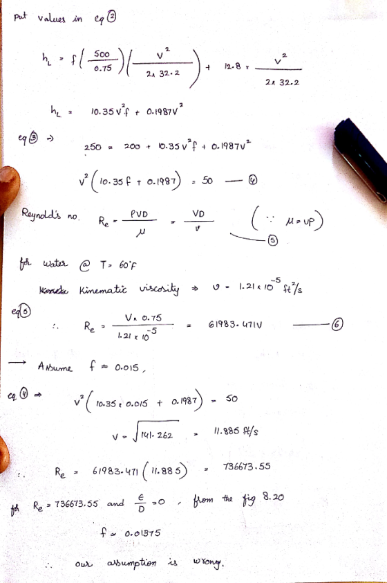
![The pump shown in Figure delivers a head of 250 ft to the water. One wants to determine the power that the pump adds to the water. The difference in elevation of the two ponds is 200 ft Assume Re 7.7 x 10⁵, Density is 1.94 slug/ft? and viscosity is 2.34x10%bs/ft2 a. State assumptions and setup Bernoulli equation between two reservoirs (5 b. Derive equation which relates friction factor, f and velocity from the above result (10 c. Derive Re in term of velocity [5] d. Calculate velocity, Re and friction factor via trial and error [15] e. Calculate major and minor losses [10) f. Calculate the pump power [5] Pump K,1.5 Lelbow 5.0 Pipe length 500 ft Pipe diameter 0.75 ft K, Lvalve Kn 0.8 Pipe roughness0 ent](http://img.homeworklib.com/questions/615f12c0-981c-11eb-aa7f-2726f5099a5c.png?x-oss-process=image/resize,w_560)
Fluid mechanics.
please answer all the questions.
Homework Answers


Add Answer to:
Fluid mechanics.
please answer all the questions.
The pump shown in Figure delivers a head of...
(Q1) The piping system shown here has a pump that delivers 10 hp to the fluid...
 (Q1) The piping system shown here has a pump that delivers 10 hp to the fluid ant a flow rate of 55 gpm of water at 80 F. Neglecting other losses, (a) evaluate the friction losses in the 272 ft-long discharge pipe and in the 12 ft- long suction pipe. (b) Calculate the pressure (psig) on top of the discharge tank. ...(25 marks) an 7 1.5 in Schedule 80 pipe 220 2 in Schedule 80 pipe
solve both parts a and b please A centrifugal pump having a head capacity relationship given...
 solve both parts a and b please
A centrifugal pump having a head capacity relationship given by the equation; h = 160 - 9.58x10^Q? with hain feet when Q is in gpm, is to be used with a system similar to that shown in Figure 12.14. The fluid is water. Assume the pipe diameter to be 5-in, the total length of constant-diameter pipe is 700 ft, and the friction factor to be equal to 0.022. Neglect all minor losses. For...
solve both parts a and b please
A centrifugal pump having a head capacity relationship given by the equation; h = 160 - 9.58x10^Q? with hain feet when Q is in gpm, is to be used with a system similar to that shown in Figure 12.14. The fluid is water. Assume the pipe diameter to be 5-in, the total length of constant-diameter pipe is 700 ft, and the friction factor to be equal to 0.022. Neglect all minor losses. For...
[Problem 3] Two reservoirs are connected using the piping network shown in the figure. The pipes ...
 [Problem 3] Two reservoirs are connected using the piping network shown in the figure. The pipes are commercial steel. water is to be pumped using a pump (efficiency = 70%) that draws 8 kw of electric power from the mains. Ignore minor losses. Determine the flow rate through each pipe and the total flow between the reservoirs. Start with a friction factor of 0.02 for all pipes and use the Haaland equation to calculate updated friction factors. Ignore the length...
The water pump, as shown in the figure below, maintains a pressure of 6.5 psig at...
 The water pump, as shown in the figure below, maintains a
pressure of 6.5 psig at point 1. There is a filter, a half-open
disk valve, and two regular screwed elbows. There are 80 ft of
4-inch diameter commercial steel pipe. For water, take ρ = 1.94
slug/ft3 and μ = 2.09E−5 slug/ft⋅s. Take kvalve ≈ 2.8, kelbow ≈
0.64, kexit ≈ 1, and kvalve ≈ 0 (when the disk valve wide open). If
the flow rate is 0.55 ft3/s,...
The water pump, as shown in the figure below, maintains a
pressure of 6.5 psig at point 1. There is a filter, a half-open
disk valve, and two regular screwed elbows. There are 80 ft of
4-inch diameter commercial steel pipe. For water, take ρ = 1.94
slug/ft3 and μ = 2.09E−5 slug/ft⋅s. Take kvalve ≈ 2.8, kelbow ≈
0.64, kexit ≈ 1, and kvalve ≈ 0 (when the disk valve wide open). If
the flow rate is 0.55 ft3/s,...
4. The discharge pressure gauge reading is 5 lb/in2 (psi) for the pumping system shown in the ske...
 4. The discharge pressure gauge reading is 5 lb/in2 (psi) for the pumping system shown in the sketch below, with the outlet nozzle discharging a 2-inch diameter stream of water directly to the atmosphere. The gauge pressure at the pump suction inlet at the point of incipient cavitation is (-2,071.12) lb/ft, i.e., for vapor pressure of water at 68° F of 50.54 lb/ft2 absolute, and standard atmospheric pressure 30 in Hg. Friction losses in the suction piping from the reservoir...
Two reservoirs are connected using the piping network shown in the figure. The pipes are commerci...
 Two reservoirs are connected using the piping network shown in
the figure. The pipes are commercial steel. Water is to be pumped
using a pump (efficiency = 70%) that draws 8 kW of electric power
from the mains. Ignore minor losses. Determine the flow rate
through each pipe and the total flow between the reservoirs. Start
with a friction factor of 0.02 for all pipes and use the Haaland
equation to calculate updated friction factors. Ignore the length
of the...
Two reservoirs are connected using the piping network shown in
the figure. The pipes are commercial steel. Water is to be pumped
using a pump (efficiency = 70%) that draws 8 kW of electric power
from the mains. Ignore minor losses. Determine the flow rate
through each pipe and the total flow between the reservoirs. Start
with a friction factor of 0.02 for all pipes and use the Haaland
equation to calculate updated friction factors. Ignore the length
of the...
show all work will thunbs up Problem #7(30points! A motor- driven pump reservoir, through a 2500m long, 30 cm ID plastic level in the second re en centrifugal pump delivers 15°C water at the rate...
 show all work will thunbs up
Problem #7(30points! A motor- driven pump reservoir, through a 2500m long, 30 cm ID plastic level in the second re en centrifugal pump delivers 15°C water at the rate of 10m3/min from a pipe, to a second reservoir. The water servoir is 40 m above the water level in the first reservoir. The pump efficiency is 75%. The loss coefficient of the square-edged entrance is 0.5 a) Sketch the problem and locate your point...
show all work will thunbs up
Problem #7(30points! A motor- driven pump reservoir, through a 2500m long, 30 cm ID plastic level in the second re en centrifugal pump delivers 15°C water at the rate of 10m3/min from a pipe, to a second reservoir. The water servoir is 40 m above the water level in the first reservoir. The pump efficiency is 75%. The loss coefficient of the square-edged entrance is 0.5 a) Sketch the problem and locate your point...
fluid mechanics SECTION A Petroleum distilate is pumped from one large diameter tank to another higher...
 fluid mechanics
SECTION A Petroleum distilate is pumped from one large diameter tank to another higher tank, via a pumping station in an oil refinery. The petroleum is pumped at a speed of 2 ms through a 150 m long pipeline of 100 mm internal diameter. The vertical distance pumped is 20 m. The sum of the entry, exit and other component losses is equivalent to 5 times the velocity head, Table Q1 Fluid density Friction factor f for the...
fluid mechanics
SECTION A Petroleum distilate is pumped from one large diameter tank to another higher tank, via a pumping station in an oil refinery. The petroleum is pumped at a speed of 2 ms through a 150 m long pipeline of 100 mm internal diameter. The vertical distance pumped is 20 m. The sum of the entry, exit and other component losses is equivalent to 5 times the velocity head, Table Q1 Fluid density Friction factor f for the...
anbox (31184010sents * Microsoft Word - 1-friction facto X Downloads/midcomp.pdf In fluid flow problems, the flow...
 anbox (31184010sents * Microsoft Word - 1-friction facto X Downloads/midcomp.pdf In fluid flow problems, the flow velocity in a long horizontal pipe depends on the pipe material, pipe geometry and fluid properties in addition to the pump power. For a horizontal pipe with a pump, the friction factor can be obtained from many correlations such as Colebrook-White Equation: 5.0452 Re IOR 2.8257 PDV 1 = -2 108 3.7065 +5.8506 (Re)-0.0001 (1) In which, fis the friction factor and pris the...
fluid mechanics please fast 1. (15 points) Water (p-1g/cm) is flowing in pipes shown in Figure...
 fluid mechanics please fast
1. (15 points) Water (p-1g/cm) is flowing in pipes shown in Figure below. Use Bernoull's equation to calculate velocity of water at point B. - Fluid velocity in the large diameter pipe is 1m/s. - Pressure at point 2 is measured with U-tube mercury manometer (Pmercury-13,600kg/m) - h1-0.3m, h2-6cm - assume that the acceleration gravity g-10m/s 2 Manometer shows 0.7kPa pressure Ji h1
fluid mechanics please fast
1. (15 points) Water (p-1g/cm) is flowing in pipes shown in Figure below. Use Bernoull's equation to calculate velocity of water at point B. - Fluid velocity in the large diameter pipe is 1m/s. - Pressure at point 2 is measured with U-tube mercury manometer (Pmercury-13,600kg/m) - h1-0.3m, h2-6cm - assume that the acceleration gravity g-10m/s 2 Manometer shows 0.7kPa pressure Ji h1
 (Q1) The piping system shown here has a pump that delivers 10 hp to the fluid ant a flow rate of 55 gpm of water at 80 F. Neglecting other losses, (a) evaluate the friction losses in the 272 ft-long discharge pipe and in the 12 ft- long suction pipe. (b) Calculate the pressure (psig) on top of the discharge tank. ...(25 marks) an 7 1.5 in Schedule 80 pipe 220 2 in Schedule 80 pipe
 solve both parts a and b please
A centrifugal pump having a head capacity relationship given by the equation; h = 160 - 9.58x10^Q? with hain feet when Q is in gpm, is to be used with a system similar to that shown in Figure 12.14. The fluid is water. Assume the pipe diameter to be 5-in, the total length of constant-diameter pipe is 700 ft, and the friction factor to be equal to 0.022. Neglect all minor losses. For...
solve both parts a and b please
A centrifugal pump having a head capacity relationship given by the equation; h = 160 - 9.58x10^Q? with hain feet when Q is in gpm, is to be used with a system similar to that shown in Figure 12.14. The fluid is water. Assume the pipe diameter to be 5-in, the total length of constant-diameter pipe is 700 ft, and the friction factor to be equal to 0.022. Neglect all minor losses. For...
 [Problem 3] Two reservoirs are connected using the piping network shown in the figure. The pipes are commercial steel. water is to be pumped using a pump (efficiency = 70%) that draws 8 kw of electric power from the mains. Ignore minor losses. Determine the flow rate through each pipe and the total flow between the reservoirs. Start with a friction factor of 0.02 for all pipes and use the Haaland equation to calculate updated friction factors. Ignore the length...
 The water pump, as shown in the figure below, maintains a
pressure of 6.5 psig at point 1. There is a filter, a half-open
disk valve, and two regular screwed elbows. There are 80 ft of
4-inch diameter commercial steel pipe. For water, take ρ = 1.94
slug/ft3 and μ = 2.09E−5 slug/ft⋅s. Take kvalve ≈ 2.8, kelbow ≈
0.64, kexit ≈ 1, and kvalve ≈ 0 (when the disk valve wide open). If
the flow rate is 0.55 ft3/s,...
The water pump, as shown in the figure below, maintains a
pressure of 6.5 psig at point 1. There is a filter, a half-open
disk valve, and two regular screwed elbows. There are 80 ft of
4-inch diameter commercial steel pipe. For water, take ρ = 1.94
slug/ft3 and μ = 2.09E−5 slug/ft⋅s. Take kvalve ≈ 2.8, kelbow ≈
0.64, kexit ≈ 1, and kvalve ≈ 0 (when the disk valve wide open). If
the flow rate is 0.55 ft3/s,...
 4. The discharge pressure gauge reading is 5 lb/in2 (psi) for the pumping system shown in the sketch below, with the outlet nozzle discharging a 2-inch diameter stream of water directly to the atmosphere. The gauge pressure at the pump suction inlet at the point of incipient cavitation is (-2,071.12) lb/ft, i.e., for vapor pressure of water at 68° F of 50.54 lb/ft2 absolute, and standard atmospheric pressure 30 in Hg. Friction losses in the suction piping from the reservoir...
 Two reservoirs are connected using the piping network shown in
the figure. The pipes are commercial steel. Water is to be pumped
using a pump (efficiency = 70%) that draws 8 kW of electric power
from the mains. Ignore minor losses. Determine the flow rate
through each pipe and the total flow between the reservoirs. Start
with a friction factor of 0.02 for all pipes and use the Haaland
equation to calculate updated friction factors. Ignore the length
of the...
Two reservoirs are connected using the piping network shown in
the figure. The pipes are commercial steel. Water is to be pumped
using a pump (efficiency = 70%) that draws 8 kW of electric power
from the mains. Ignore minor losses. Determine the flow rate
through each pipe and the total flow between the reservoirs. Start
with a friction factor of 0.02 for all pipes and use the Haaland
equation to calculate updated friction factors. Ignore the length
of the...
 show all work will thunbs up
Problem #7(30points! A motor- driven pump reservoir, through a 2500m long, 30 cm ID plastic level in the second re en centrifugal pump delivers 15°C water at the rate of 10m3/min from a pipe, to a second reservoir. The water servoir is 40 m above the water level in the first reservoir. The pump efficiency is 75%. The loss coefficient of the square-edged entrance is 0.5 a) Sketch the problem and locate your point...
show all work will thunbs up
Problem #7(30points! A motor- driven pump reservoir, through a 2500m long, 30 cm ID plastic level in the second re en centrifugal pump delivers 15°C water at the rate of 10m3/min from a pipe, to a second reservoir. The water servoir is 40 m above the water level in the first reservoir. The pump efficiency is 75%. The loss coefficient of the square-edged entrance is 0.5 a) Sketch the problem and locate your point...
 fluid mechanics
SECTION A Petroleum distilate is pumped from one large diameter tank to another higher tank, via a pumping station in an oil refinery. The petroleum is pumped at a speed of 2 ms through a 150 m long pipeline of 100 mm internal diameter. The vertical distance pumped is 20 m. The sum of the entry, exit and other component losses is equivalent to 5 times the velocity head, Table Q1 Fluid density Friction factor f for the...
fluid mechanics
SECTION A Petroleum distilate is pumped from one large diameter tank to another higher tank, via a pumping station in an oil refinery. The petroleum is pumped at a speed of 2 ms through a 150 m long pipeline of 100 mm internal diameter. The vertical distance pumped is 20 m. The sum of the entry, exit and other component losses is equivalent to 5 times the velocity head, Table Q1 Fluid density Friction factor f for the...
 anbox (31184010sents * Microsoft Word - 1-friction facto X Downloads/midcomp.pdf In fluid flow problems, the flow velocity in a long horizontal pipe depends on the pipe material, pipe geometry and fluid properties in addition to the pump power. For a horizontal pipe with a pump, the friction factor can be obtained from many correlations such as Colebrook-White Equation: 5.0452 Re IOR 2.8257 PDV 1 = -2 108 3.7065 +5.8506 (Re)-0.0001 (1) In which, fis the friction factor and pris the...
 fluid mechanics please fast
1. (15 points) Water (p-1g/cm) is flowing in pipes shown in Figure below. Use Bernoull's equation to calculate velocity of water at point B. - Fluid velocity in the large diameter pipe is 1m/s. - Pressure at point 2 is measured with U-tube mercury manometer (Pmercury-13,600kg/m) - h1-0.3m, h2-6cm - assume that the acceleration gravity g-10m/s 2 Manometer shows 0.7kPa pressure Ji h1
fluid mechanics please fast
1. (15 points) Water (p-1g/cm) is flowing in pipes shown in Figure below. Use Bernoull's equation to calculate velocity of water at point B. - Fluid velocity in the large diameter pipe is 1m/s. - Pressure at point 2 is measured with U-tube mercury manometer (Pmercury-13,600kg/m) - h1-0.3m, h2-6cm - assume that the acceleration gravity g-10m/s 2 Manometer shows 0.7kPa pressure Ji h1
Most questions answered within 3 hours.
-
Where is the error in this code sequence?
String s1 = "Hello";
String s2 = "ello";...
asked 10 months ago -
Financial data for Joel de Paris, Inc., for last year
follow:
Joel de Paris, Inc.
Balance...
asked 10 months ago -
Consider this reaction:
Al2(SO4)3 (aq)+ BaCl3
(aq) Al2Cl6 (aq)- +
3BaSO4(s) . What is the...
asked 10 months ago -
Suppose that Savneet is considering increasing her
recent random sample from 20 car rentals to 40...
asked 10 months ago -
Trucks arrive at an unloading terminal at an average rate of 120
per hour.
Trucks arrive...
asked 10 months ago -
Why are methanol and ethanol completely soluble in water while
octanol is not very little soluble....
asked 10 months ago -
A facilities manager at a university reads in a research report
that the mean amount of...
asked 10 months ago -
When the CuSO4 is rehydrated by adding water to the anhydrous
compound, is this an endothermic...
asked 10 months ago -
A ray of sunlight is passing from diamond into crown glass; the
angle of incidence is...
asked 10 months ago -
A block of mass 0.249 kg is placed on top of a light, vertical
spring of...
asked 10 months ago -
how do the kidneys compensate in the presences of acidosis
a) trigger hyperventilate
b) reserve acid...
asked 10 months ago -
Question 501 pts
The rental rate of capital to the firm increases. Which of the
following...
asked 10 months ago