
Homework Answers

Add Answer to:
Determine the normal stresses at A and B. 5, 12 kN 140 mm A B width...
M8.20 C-clamp normal stresses scenes Width 140 mm 16 kN Thickness 22 mm 55 mm B...
 M8.20 C-clamp normal stresses scenes Width 140 mm 16 kN Thickness 22 mm 55 mm B CA (MPa) Determine the normal stresses at A and B (+ = tension, compression). -= Ов (MPа) Try one 1st 2nd 3rd enter attempt
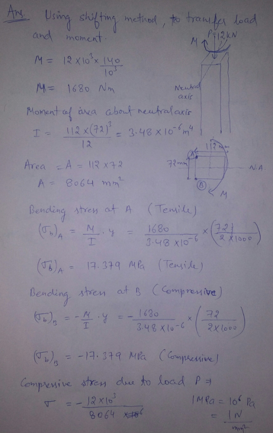
scenes M8.21 Precast concrete beam and corbel 12 kN 130 mm Determine the normal stresses at...
 scenes M8.21 Precast concrete beam and corbel 12 kN 130 mm Determine the normal stresses at H and K (+ = tension,-= compression). H. K Width 96 mm Thickness 64 mm Pa 1 st 2nd 3rd attempt enter Try one MecMovies (0 Timothy A. Philpot 2001-2017
A column with a wide-flange section has a flange width b = 400 mm , height...
 A column with a wide-flange section has a flange width
b = 400 mm , height h = 400 mm , web thickness
tw = 13 mm , and flange thickness
tf = 21 mm (Figure 1). Calculate the stresses at
a point 65 mm above the neutral axis if the section supports a
tensile normal force N = 3 kN at the centroid, shear force
V = 7.4 kN , and bending moment M = 4 kN⋅m as
shown...
A column with a wide-flange section has a flange width
b = 400 mm , height h = 400 mm , web thickness
tw = 13 mm , and flange thickness
tf = 21 mm (Figure 1). Calculate the stresses at
a point 65 mm above the neutral axis if the section supports a
tensile normal force N = 3 kN at the centroid, shear force
V = 7.4 kN , and bending moment M = 4 kN⋅m as
shown...
The machine element below is in static equilibrium. Determine the shear and normal stresses at H...
 The machine element below is in static equilibrium.
Determine the shear and normal stresses at H and G, and draw the
stress states at both locations.
50 kN 130 mm 75 kN 100 mm Dr. 1 30 kN 25 mm 200 mm 70 mm 140 mm 40 mm 20 mm
The machine element below is in static equilibrium.
Determine the shear and normal stresses at H and G, and draw the
stress states at both locations.
50 kN 130 mm 75 kN 100 mm Dr. 1 30 kN 25 mm 200 mm 70 mm 140 mm 40 mm 20 mm
Question 5 16 pts The steel pipe AB has a 72-mm outer diameter and a 5-mm...
 Question 5 16 pts The steel pipe AB has a 72-mm outer diameter and a 5-mm wall thickness. Knowing that the arm CDE is rigidly attached to the pipe, determine the normal and shearing stresses at point H on the outer surface. The properties at the cross section at H include: A 1052.4 mm2,J 1,187,700 mm4, 1 593,840 mm4, and QNA 11,243 mm3 3 kN 9 kN 120 mm 150 mm 120 mm a.) Normal stress at H: b.) Shear...
Determine maximal normal stresses, if the force parameter F is equal 5 kN ww 15F 16...
 Determine maximal normal stresses, if the force parameter F is equal 5 kN ww 15F 16 2F 8.0 3F 10 100 cm 0ST
Determine maximal normal stresses, if the force parameter F is equal 5 kN ww 15F 16 2F 8.0 3F 10 100 cm 0ST
Determine maximal normal stresses, if the force parameter F is equal 5 kN ww 15F 16 2F 8.0 3F 10 100 cm 0ST
60 mm high, 40 mm wide plate with a thickness of 5 mm is loaded as...
 60 mm high, 40 mm wide plate with a thickness of 5 mm is loaded
as shown in the figure below. a) Use Mohr's circle to determine the
normal and shear stresses along the diagonal AC. Show the stress
state on the Mohr circle. b) Sketch an element showing the maximum
shear stress state.
10 kN 60 mmvai 30 kN Ą I PK > 5 mm 40 mm
60 mm high, 40 mm wide plate with a thickness of 5 mm is loaded
as shown in the figure below. a) Use Mohr's circle to determine the
normal and shear stresses along the diagonal AC. Show the stress
state on the Mohr circle. b) Sketch an element showing the maximum
shear stress state.
10 kN 60 mmvai 30 kN Ą I PK > 5 mm 40 mm
draw mohr circle 3 kN/m 300 mm 30° 75 mm 200 mm Determine the principal stresses...
 draw mohr circle
3 kN/m 300 mm 30° 75 mm 200 mm Determine the principal stresses at point A and specify the orientation of element. PROBLEM # 5 FA-3x4-12kN 2m Br B, 3.428 kN 2m 3.428KN -May. = 6.857 x 1-75 = 1.1428 N/mm"(7) mm (7) 200:300厂= 1.1428 N/ mm 300 12 bi 4 0.06428 N/mm2 6x3.4428x10 300 ) 200x 300 4 200
draw mohr circle
3 kN/m 300 mm 30° 75 mm 200 mm Determine the principal stresses at point A and specify the orientation of element. PROBLEM # 5 FA-3x4-12kN 2m Br B, 3.428 kN 2m 3.428KN -May. = 6.857 x 1-75 = 1.1428 N/mm"(7) mm (7) 200:300厂= 1.1428 N/ mm 300 12 bi 4 0.06428 N/mm2 6x3.4428x10 300 ) 200x 300 4 200
For the joint and loading shown, determine the stress states at points A and B on...
 For the joint and loading shown, determine the stress states at
points A and B on section-aa, and the principle stresses at point
A. The free-body diagram including section-aa is given below for
your convenience. Section-aa has a rectangular cross-section area
of thickness 12 mm (shown) and width 18 mm. a) Sketch each stress
state using a square stress element. b) Determine the principle
stresses at point A (no need to sketch the stress
element).
Problem 1: (25%) For the...
For the joint and loading shown, determine the stress states at
points A and B on section-aa, and the principle stresses at point
A. The free-body diagram including section-aa is given below for
your convenience. Section-aa has a rectangular cross-section area
of thickness 12 mm (shown) and width 18 mm. a) Sketch each stress
state using a square stress element. b) Determine the principle
stresses at point A (no need to sketch the stress
element).
Problem 1: (25%) For the...
M5.8 Rigid bar with opposing members scenes Determine the internal forces and normal stresses in bars...
 M5.8 Rigid bar with opposing members scenes Determine the internal forces and normal stresses in bars (1) and (2). (+ = tension, - = compression) Bar properties Also, determine the deflection of the rigid bar in the 300 mm x direction at c. Ey = 140 GPa 600 mm Az = 300 mm 140 GPa A, = (2) F. (kN) 610 mm F (kN) 40 KN (MPa) 810 mm (MPa) 750 mm 610 mm V mm 1 2 3 attempt...
 M8.20 C-clamp normal stresses scenes Width 140 mm 16 kN Thickness 22 mm 55 mm B CA (MPa) Determine the normal stresses at A and B (+ = tension, compression). -= Ов (MPа) Try one 1st 2nd 3rd enter attempt
 scenes M8.21 Precast concrete beam and corbel 12 kN 130 mm Determine the normal stresses at H and K (+ = tension,-= compression). H. K Width 96 mm Thickness 64 mm Pa 1 st 2nd 3rd attempt enter Try one MecMovies (0 Timothy A. Philpot 2001-2017
 A column with a wide-flange section has a flange width
b = 400 mm , height h = 400 mm , web thickness
tw = 13 mm , and flange thickness
tf = 21 mm (Figure 1). Calculate the stresses at
a point 65 mm above the neutral axis if the section supports a
tensile normal force N = 3 kN at the centroid, shear force
V = 7.4 kN , and bending moment M = 4 kN⋅m as
shown...
A column with a wide-flange section has a flange width
b = 400 mm , height h = 400 mm , web thickness
tw = 13 mm , and flange thickness
tf = 21 mm (Figure 1). Calculate the stresses at
a point 65 mm above the neutral axis if the section supports a
tensile normal force N = 3 kN at the centroid, shear force
V = 7.4 kN , and bending moment M = 4 kN⋅m as
shown...
 The machine element below is in static equilibrium.
Determine the shear and normal stresses at H and G, and draw the
stress states at both locations.
50 kN 130 mm 75 kN 100 mm Dr. 1 30 kN 25 mm 200 mm 70 mm 140 mm 40 mm 20 mm
The machine element below is in static equilibrium.
Determine the shear and normal stresses at H and G, and draw the
stress states at both locations.
50 kN 130 mm 75 kN 100 mm Dr. 1 30 kN 25 mm 200 mm 70 mm 140 mm 40 mm 20 mm
 Question 5 16 pts The steel pipe AB has a 72-mm outer diameter and a 5-mm wall thickness. Knowing that the arm CDE is rigidly attached to the pipe, determine the normal and shearing stresses at point H on the outer surface. The properties at the cross section at H include: A 1052.4 mm2,J 1,187,700 mm4, 1 593,840 mm4, and QNA 11,243 mm3 3 kN 9 kN 120 mm 150 mm 120 mm a.) Normal stress at H: b.) Shear...
 Determine maximal normal stresses, if the force parameter F is equal 5 kN ww 15F 16 2F 8.0 3F 10 100 cm 0ST
Determine maximal normal stresses, if the force parameter F is equal 5 kN ww 15F 16 2F 8.0 3F 10 100 cm 0ST
Determine maximal normal stresses, if the force parameter F is equal 5 kN ww 15F 16 2F 8.0 3F 10 100 cm 0ST
 60 mm high, 40 mm wide plate with a thickness of 5 mm is loaded
as shown in the figure below. a) Use Mohr's circle to determine the
normal and shear stresses along the diagonal AC. Show the stress
state on the Mohr circle. b) Sketch an element showing the maximum
shear stress state.
10 kN 60 mmvai 30 kN Ą I PK > 5 mm 40 mm
60 mm high, 40 mm wide plate with a thickness of 5 mm is loaded
as shown in the figure below. a) Use Mohr's circle to determine the
normal and shear stresses along the diagonal AC. Show the stress
state on the Mohr circle. b) Sketch an element showing the maximum
shear stress state.
10 kN 60 mmvai 30 kN Ą I PK > 5 mm 40 mm
 draw mohr circle
3 kN/m 300 mm 30° 75 mm 200 mm Determine the principal stresses at point A and specify the orientation of element. PROBLEM # 5 FA-3x4-12kN 2m Br B, 3.428 kN 2m 3.428KN -May. = 6.857 x 1-75 = 1.1428 N/mm"(7) mm (7) 200:300厂= 1.1428 N/ mm 300 12 bi 4 0.06428 N/mm2 6x3.4428x10 300 ) 200x 300 4 200
draw mohr circle
3 kN/m 300 mm 30° 75 mm 200 mm Determine the principal stresses at point A and specify the orientation of element. PROBLEM # 5 FA-3x4-12kN 2m Br B, 3.428 kN 2m 3.428KN -May. = 6.857 x 1-75 = 1.1428 N/mm"(7) mm (7) 200:300厂= 1.1428 N/ mm 300 12 bi 4 0.06428 N/mm2 6x3.4428x10 300 ) 200x 300 4 200
 For the joint and loading shown, determine the stress states at
points A and B on section-aa, and the principle stresses at point
A. The free-body diagram including section-aa is given below for
your convenience. Section-aa has a rectangular cross-section area
of thickness 12 mm (shown) and width 18 mm. a) Sketch each stress
state using a square stress element. b) Determine the principle
stresses at point A (no need to sketch the stress
element).
Problem 1: (25%) For the...
For the joint and loading shown, determine the stress states at
points A and B on section-aa, and the principle stresses at point
A. The free-body diagram including section-aa is given below for
your convenience. Section-aa has a rectangular cross-section area
of thickness 12 mm (shown) and width 18 mm. a) Sketch each stress
state using a square stress element. b) Determine the principle
stresses at point A (no need to sketch the stress
element).
Problem 1: (25%) For the...
 M5.8 Rigid bar with opposing members scenes Determine the internal forces and normal stresses in bars (1) and (2). (+ = tension, - = compression) Bar properties Also, determine the deflection of the rigid bar in the 300 mm x direction at c. Ey = 140 GPa 600 mm Az = 300 mm 140 GPa A, = (2) F. (kN) 610 mm F (kN) 40 KN (MPa) 810 mm (MPa) 750 mm 610 mm V mm 1 2 3 attempt...
Most questions answered within 3 hours.
-
Where is the error in this code sequence?
String s1 = "Hello";
String s2 = "ello";...
asked 10 months ago -
Financial data for Joel de Paris, Inc., for last year
follow:
Joel de Paris, Inc.
Balance...
asked 10 months ago -
Consider this reaction:
Al2(SO4)3 (aq)+ BaCl3
(aq) Al2Cl6 (aq)- +
3BaSO4(s) . What is the...
asked 10 months ago -
Suppose that Savneet is considering increasing her
recent random sample from 20 car rentals to 40...
asked 10 months ago -
Trucks arrive at an unloading terminal at an average rate of 120
per hour.
Trucks arrive...
asked 10 months ago -
Why are methanol and ethanol completely soluble in water while
octanol is not very little soluble....
asked 10 months ago -
A facilities manager at a university reads in a research report
that the mean amount of...
asked 10 months ago -
When the CuSO4 is rehydrated by adding water to the anhydrous
compound, is this an endothermic...
asked 10 months ago -
A ray of sunlight is passing from diamond into crown glass; the
angle of incidence is...
asked 10 months ago -
A block of mass 0.249 kg is placed on top of a light, vertical
spring of...
asked 10 months ago -
how do the kidneys compensate in the presences of acidosis
a) trigger hyperventilate
b) reserve acid...
asked 10 months ago -
Question 501 pts
The rental rate of capital to the firm increases. Which of the
following...
asked 10 months ago