Determine the angle of twist at end A of the tubular shaft relative to end C....
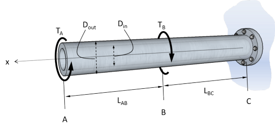
Determine the angle of twist at end A of the tubular shaft relative to end C. Include the proper sign (- or +) on your answer using
the right-hand rule and the axis shown.
TA = 7 kN-m
TB = 20 kN-m
LAB = 0.75 m
LBC = 0.8 m
DOut = 60 mm
DIn = 45 mm
G = 90 GPa
ϕ = Incorrect
| Your Answer: | -3.513 |
|---|
I keep getting the wrong answer. I need some assistant, please
Homework Answers
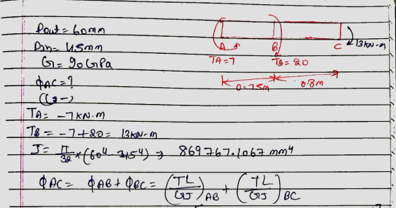
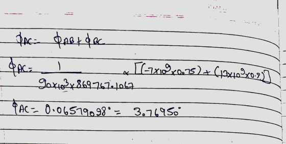
Add Answer to:
Determine the angle of twist at end A of the tubular shaft
relative to end C....
4. For the solid steel shaft shown in the figure, determine the angle of twist at...
 4. For the solid steel shaft shown in the figure, determine the angle of twist at A. Use G-70 GPa. The cylinder has a diameter of 40 mm. 2m 400 N m
The 50-mm-diameter solid shaft is made of A-36 steel and is subjected to the distributed and...
 The 50-mm-diameter solid shaft is made of A-36 steel and is subjected to the distributed and concentrated torsional loadings shown where T = 140 N-m. 2 kNm 600 Nm B 0.8 m 0.6 m A Part A Determine the angle of twist at the free end A of the shaft due to these loadings. Use Gst = 75.0 GPa Express your answer to three significant figures and include appropriate units. μΑ ? 22 % Å O 0.303 Submit Previous Answers...
The 50-mm-diameter solid shaft is made of A-36 steel and is subjected to the distributed and...
 The 50-mm-diameter solid shaft is made of A-36 steel and is subjected to the distributed and concentrated torsional loadings shown where T = 140 N-m. 2 kNm 600 Nm B 0.8 m 0.6 m A Part A Determine the angle of twist at the free end A of the shaft due to these loadings. Use Gst = 75.0 GPa Express your answer to three significant figures and include appropriate units. μΑ ? 22 % Å O 0.303 Submit Previous Answers...
The 50-mm-diameter solid shaft is made of A-36 steel and is subjected to the distributed and...
 The 50-mm-diameter solid shaft is made of A-36 steel and is subjected to the distributed and concentrated torsional loadings shown where T = 140 N-m. 2 kNm 600 Nm B 0.8 m 0.6 m A Part A Determine the angle of twist at the free end A of the shaft due to these loadings. Use Gst = 75.0 GPa Express your answer to three significant figures and include appropriate units. μΑ ? 22 % Å O 0.303 Submit Previous Answers...
The hollow 6061-T6 aluminum shaft has an outer and inner radius of co = 40 mm and ci = 30 mm, respectively. Take G = 26...
 The hollow 6061-T6 aluminum shaft has an outer and inner radius
of co = 40 mm and ci = 30 mm, respectively. Take G = 26 GPa.
Determine the angle of twist of end A. The flexible support at B
has a torsional stiffness of k = 97 kN⋅m/rad .
Express your answer to three significant figures and include the
appropriate units.
900 mm 3 kN m
900 mm 3 kN m
The hollow 6061-T6 aluminum shaft has an outer and inner radius
of co = 40 mm and ci = 30 mm, respectively. Take G = 26 GPa.
Determine the angle of twist of end A. The flexible support at B
has a torsional stiffness of k = 97 kN⋅m/rad .
Express your answer to three significant figures and include the
appropriate units.
900 mm 3 kN m
900 mm 3 kN m
Learning Goal: To determine the angle of twist on a composite rod given the geometry and...
 Learning Goal: To determine the angle of twist on a composite rod given the geometry and externally applied torques, to properly apply a sign convention to determine the angle of twist, to use a torque diagram to aid in determining the angle of twist, and to determine the maximum applicable torque given a maximum allowable angle of twist. The rod shown below is made of two different materials. Segment AB is made of aluminum (G=27 GPa). Segment BC is bonded...
The 50-mm-diameter solid shaft is made of A-36 steel and is subjected to the distributed and...
 The 50-mm-diameter solid shaft is made of A-36 steel and is subjected to the distributed and concentrated torsional loadings shown where T = 230 N-m. 2 kNm 600 Nm B 0.8 m 0.6 m Part A Determine the angle of twist at the free end A of the shaft due to these loadings. Use Gst = 75.0 GPa Express your answer to three significant figures and include appropriate units. μΑ ? O= Value Units
Part A Determine the displacement of end A with respect to and D if the diameters...
 Part A Determine the displacement of end A with respect to and D if the diameters of each segment are dam = 19 mm, dec = 26 mm, dcp = 14 mm. Take Ec= 126 GPa. the case contraction and positive Express your answer to three significant figures and include the appropriate units. Enter negative value value in the case of elongation. ? Value Units 225 The copper shaft is subjected to the axial loads shown in (Figure 1). Figure...
B-220 GPa and I - 650(109) mm (Figure 1) Part A Determine the slope of end...
 B-220 GPa and I - 650(109) mm (Figure 1) Part A Determine the slope of end of the cantilevered beam Express your answer to three significant figures and include the appropriate units. | HÁ ? Figure 1 of 1 > Value Units 10 KN 3 N/m Submit Previous Answers Request Answer * Incorrect; Try Again; 3 attempts remaining Provide Feedback
4. Determine the slope and deflection at end point C of the cantilever beam shown in...
 4. Determine the slope and deflection at end point C of the cantilever beam shown in the figure. Use E = 200 GPa, I = 10 x 106 mm 3 kN/m 2 kN.m A B 2 m 2 m
 4. For the solid steel shaft shown in the figure, determine the angle of twist at A. Use G-70 GPa. The cylinder has a diameter of 40 mm. 2m 400 N m
 The 50-mm-diameter solid shaft is made of A-36 steel and is subjected to the distributed and concentrated torsional loadings shown where T = 140 N-m. 2 kNm 600 Nm B 0.8 m 0.6 m A Part A Determine the angle of twist at the free end A of the shaft due to these loadings. Use Gst = 75.0 GPa Express your answer to three significant figures and include appropriate units. μΑ ? 22 % Å O 0.303 Submit Previous Answers...
 The 50-mm-diameter solid shaft is made of A-36 steel and is subjected to the distributed and concentrated torsional loadings shown where T = 140 N-m. 2 kNm 600 Nm B 0.8 m 0.6 m A Part A Determine the angle of twist at the free end A of the shaft due to these loadings. Use Gst = 75.0 GPa Express your answer to three significant figures and include appropriate units. μΑ ? 22 % Å O 0.303 Submit Previous Answers...
 The 50-mm-diameter solid shaft is made of A-36 steel and is subjected to the distributed and concentrated torsional loadings shown where T = 140 N-m. 2 kNm 600 Nm B 0.8 m 0.6 m A Part A Determine the angle of twist at the free end A of the shaft due to these loadings. Use Gst = 75.0 GPa Express your answer to three significant figures and include appropriate units. μΑ ? 22 % Å O 0.303 Submit Previous Answers...
 The hollow 6061-T6 aluminum shaft has an outer and inner radius
of co = 40 mm and ci = 30 mm, respectively. Take G = 26 GPa.
Determine the angle of twist of end A. The flexible support at B
has a torsional stiffness of k = 97 kN⋅m/rad .
Express your answer to three significant figures and include the
appropriate units.
900 mm 3 kN m
900 mm 3 kN m
The hollow 6061-T6 aluminum shaft has an outer and inner radius
of co = 40 mm and ci = 30 mm, respectively. Take G = 26 GPa.
Determine the angle of twist of end A. The flexible support at B
has a torsional stiffness of k = 97 kN⋅m/rad .
Express your answer to three significant figures and include the
appropriate units.
900 mm 3 kN m
900 mm 3 kN m
 Learning Goal: To determine the angle of twist on a composite rod given the geometry and externally applied torques, to properly apply a sign convention to determine the angle of twist, to use a torque diagram to aid in determining the angle of twist, and to determine the maximum applicable torque given a maximum allowable angle of twist. The rod shown below is made of two different materials. Segment AB is made of aluminum (G=27 GPa). Segment BC is bonded...
 The 50-mm-diameter solid shaft is made of A-36 steel and is subjected to the distributed and concentrated torsional loadings shown where T = 230 N-m. 2 kNm 600 Nm B 0.8 m 0.6 m Part A Determine the angle of twist at the free end A of the shaft due to these loadings. Use Gst = 75.0 GPa Express your answer to three significant figures and include appropriate units. μΑ ? O= Value Units
 Part A Determine the displacement of end A with respect to and D if the diameters of each segment are dam = 19 mm, dec = 26 mm, dcp = 14 mm. Take Ec= 126 GPa. the case contraction and positive Express your answer to three significant figures and include the appropriate units. Enter negative value value in the case of elongation. ? Value Units 225 The copper shaft is subjected to the axial loads shown in (Figure 1). Figure...
 B-220 GPa and I - 650(109) mm (Figure 1) Part A Determine the slope of end of the cantilevered beam Express your answer to three significant figures and include the appropriate units. | HÁ ? Figure 1 of 1 > Value Units 10 KN 3 N/m Submit Previous Answers Request Answer * Incorrect; Try Again; 3 attempts remaining Provide Feedback
 4. Determine the slope and deflection at end point C of the cantilever beam shown in the figure. Use E = 200 GPa, I = 10 x 106 mm 3 kN/m 2 kN.m A B 2 m 2 m
Most questions answered within 3 hours.
-
Where is the error in this code sequence?
String s1 = "Hello";
String s2 = "ello";...
asked 11 months ago -
Financial data for Joel de Paris, Inc., for last year
follow:
Joel de Paris, Inc.
Balance...
asked 11 months ago -
Consider this reaction:
Al2(SO4)3 (aq)+ BaCl3
(aq) Al2Cl6 (aq)- +
3BaSO4(s) . What is the...
asked 11 months ago -
Suppose that Savneet is considering increasing her
recent random sample from 20 car rentals to 40...
asked 11 months ago -
Trucks arrive at an unloading terminal at an average rate of 120
per hour.
Trucks arrive...
asked 11 months ago -
Why are methanol and ethanol completely soluble in water while
octanol is not very little soluble....
asked 11 months ago -
A facilities manager at a university reads in a research report
that the mean amount of...
asked 11 months ago -
When the CuSO4 is rehydrated by adding water to the anhydrous
compound, is this an endothermic...
asked 11 months ago -
A ray of sunlight is passing from diamond into crown glass; the
angle of incidence is...
asked 11 months ago -
A block of mass 0.249 kg is placed on top of a light, vertical
spring of...
asked 11 months ago -
how do the kidneys compensate in the presences of acidosis
a) trigger hyperventilate
b) reserve acid...
asked 11 months ago -
Question 501 pts
The rental rate of capital to the firm increases. Which of the
following...
asked 11 months ago